
Methods and apparatus for detecting ventricular depolarizations during atrial pacing

a ventricular depolarization and atrial pacing technology, applied in the field of atrial pacing synchronization and dual chamber pacing systems, can solve the problems of false a-event or v-event declaration, inability to use sense amplifiers to detect capture or loss of capture (loc) of the atria and ventricles, and inability to declare a v-event by the ventricular sense amplifier, so as to achieve more robust v-event sens

Inactive Publication Date: 2010-10-05
MEDTRONIC INC
View PDF36 Cites 0 Cited by
  • Summary
  • Abstract
  • Description
  • Claims
  • Application Information

AI Technical Summary

Benefits of technology

[0035]The QRS complex of such a PVC that appears between tightly spaced, near field, ventricular pace / sense electrodes is relatively narrow and exhibits a pronounced R-wave peak that is excellent for ventricular sensing when the ventricular sense amplifier is not blanked. Accordingly, the ventricular sense amplifier is preferably coupled with bipolar pace / sense electrodes and advantageously provides robust sensing of PVCs or conducted R-waves when it is not blanked. However, the narrow QRS complex sensed across the closely spaced ventricular pace / sense electrodes dissipates by the time that the PAVBP times-out as the depolarization wave front propagates through the ventricles and past the ventricular pace / sense electrodes. Therefore, the R-wave peak of a PVC occurring within the PAVBP is not sensed by the ventricular sense amplifier when the PAVBP times-out. A need therefore remains for a capability of sensing such PVCs falling within the PAVBP
[0036]We have observed that the QRS complexes of such PVCs observed across widely spaced sense electrodes are relatively wide and are less susceptible to under-sensing during the PAVBP. We have also observed that sense electrodes that are spatially separated from the ventricular pace / sense electrodes add additional sensing capabilities because of the propagation delay of the QRS wavefront between such remote electrodes. In accordance with the present invention, a PVC occurring coincident with or shortly following delivery of an A-PACE pulse that would fall within the PAVBP is sensed employing a PVC sense amplifier that is coupled to such widely spaced sense electrodes that do not include both of the ventricular pace / sense electrodes coupled to the ventricular sense amplifier subjected to the PAVBP. The PVC sense amplifier may be blanked simply during delivery of the A-PACE pulse to protect the sense amplifier circuitry from the applied pacing voltage, but can then sense the relatively wide QRS complex of the PVC that persists longer than the A-PACE pulse.
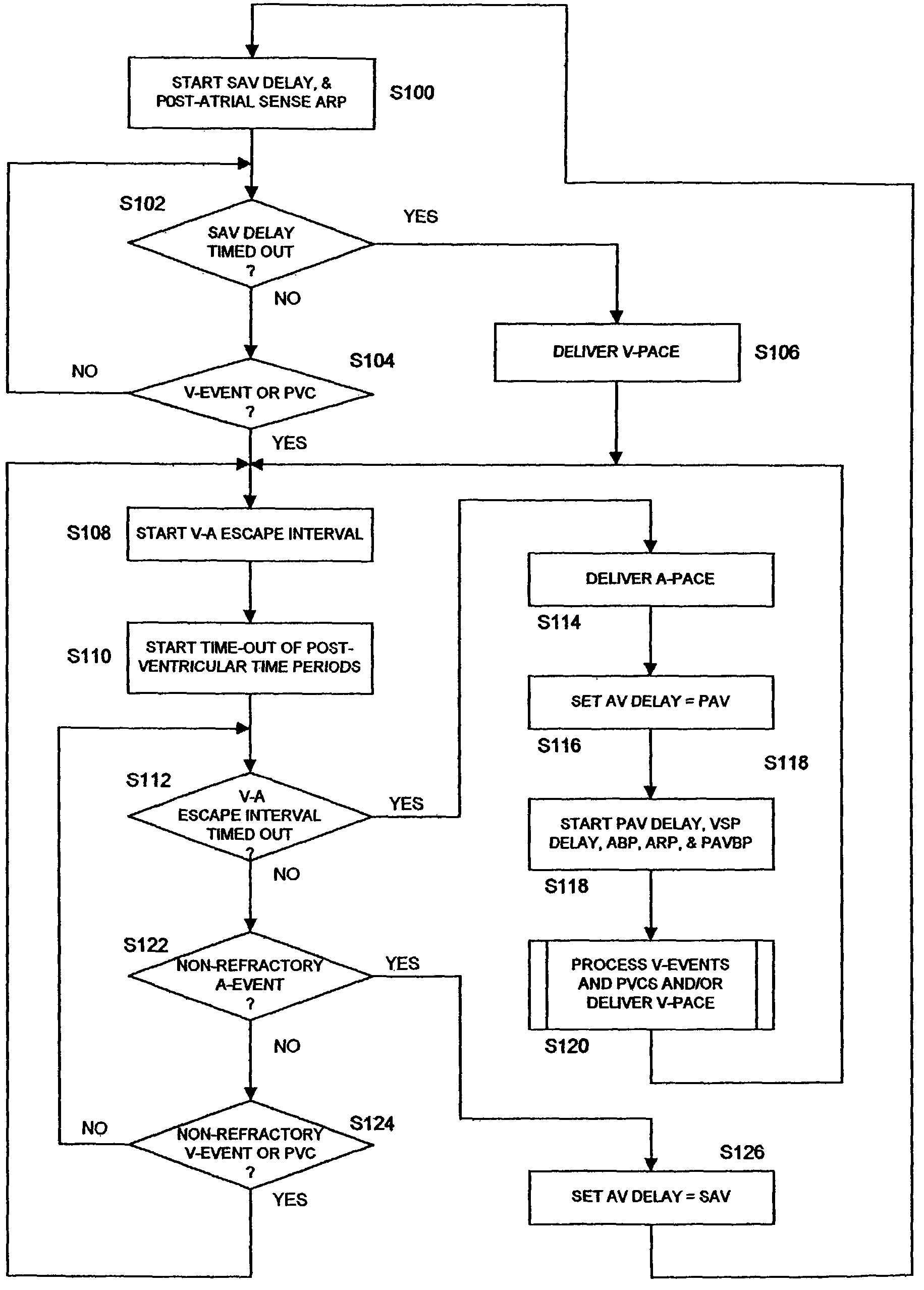
[0038]In another aspect of the present invention, the VSP function is advantageously augmented by the redundant sensing capability provided by the first ventricular sense amplifier and the PVC sense amplifier. As described above, when a PVC is under-sensed in a dual chamber pacing system, a V-PACE pulse is delivered at the end of the AV interval. At nominal AV intervals, the ventricle is typically refractory to a subsequent V-PACE pulse. However, a V-PACE pulse delivered after a long AV interval has a greater probability of capturing the heart. The V-PACE pulse may be delivered within a patient's vulnerable period and in certain circumstances may initiate an arrhythmia in a susceptible patient. The mounting evidence suggesting long-term deleterious effects of right ventricular apical pacing may increase physician motivation to extend the AV interval to decrease ventricular pacing. Ventricular safety pacing ensures a ventricular beat for each cardiac cycle and ensures that the V-PACE pulse is not delivered in the ventricular vulnerable period. This is accomplished by delivering the VSP pulse shortly after the A-PACE pulse when a V-EVENT is detected closely following the delivery of the A-PACE pulse. The subsequent VSP pulse will capture the heart if a V-EVENT was declared due to noise, but the subsequent VSP pulse will not capture the heart if the V-EVENT was due to sensing of a PVC. In accordance with this aspect of the present invention, a VSP pulse is delivered if either of the ventricular sense amplifier that is subjected to the PAVBP or the PVC sense amplifier declares a V-EVENT. In this way, the sensing of such PVCs occurring coincident with the delivery of A-PACE pulses is improved and the potential for ventricular pacing during the vulnerable period is minimized.
[0041]As noted above, the ability to detect a PVC during the PAVBP can be employed advantageously to trigger VSP pacing or to inhibit ventricular pacing, which in either case avoids delivery of a V-PACE pulse at the time-out of the PAV delay possibly into the vulnerable period of the heart cycle. The ability to detect a PVC at other times during the PAV or SAV delay or the V-A interval can advantageously be employed to confirm declarations of V-EVENTs, leading to more robust V-EVENT sensing.

Problems solved by technology

This can produce unwanted oversensing of artifacts resulting in false declarations of A-EVENTs or V-EVENTs.
One difficulty that arises from use of the blanking and refractory periods relates to the inability to use the sense amplifiers to detect the capture or loss of capture (LOC) of the atria and ventricles.
As noted above, after-potentials on the ventricular pace / sense electrodes at time-out of the PAVBP can erroneously be detected and result in declaration of a V-EVENT by the ventricular sense amplifier.
The pacing system will not provide appropriate ventricular pacing to a patient's heart having AV block if electrical noise or other signals are mistakenly sensed by the ventricular sense amplifier as V-EVENTS during time-out of the AV delay.
However, it frequently happens that the depolarization wavefront of a PVC reaches the pace / sense electrodes during the PAVBP, and the ventricular sense amplifier does not detect the R-wave.

Method used


Image

  • Methods and apparatus for detecting ventricular depolarizations during atrial pacing
  • Methods and apparatus for detecting ventricular depolarizations during atrial pacing
  • Methods and apparatus for detecting ventricular depolarizations during atrial pacing

Examples


Embodiment Construction

[0055]In the following detailed description, references are made to illustrative embodiments of methods and apparatus for carrying out the invention. It is understood that other embodiments can be utilized without departing from the scope of the invention.

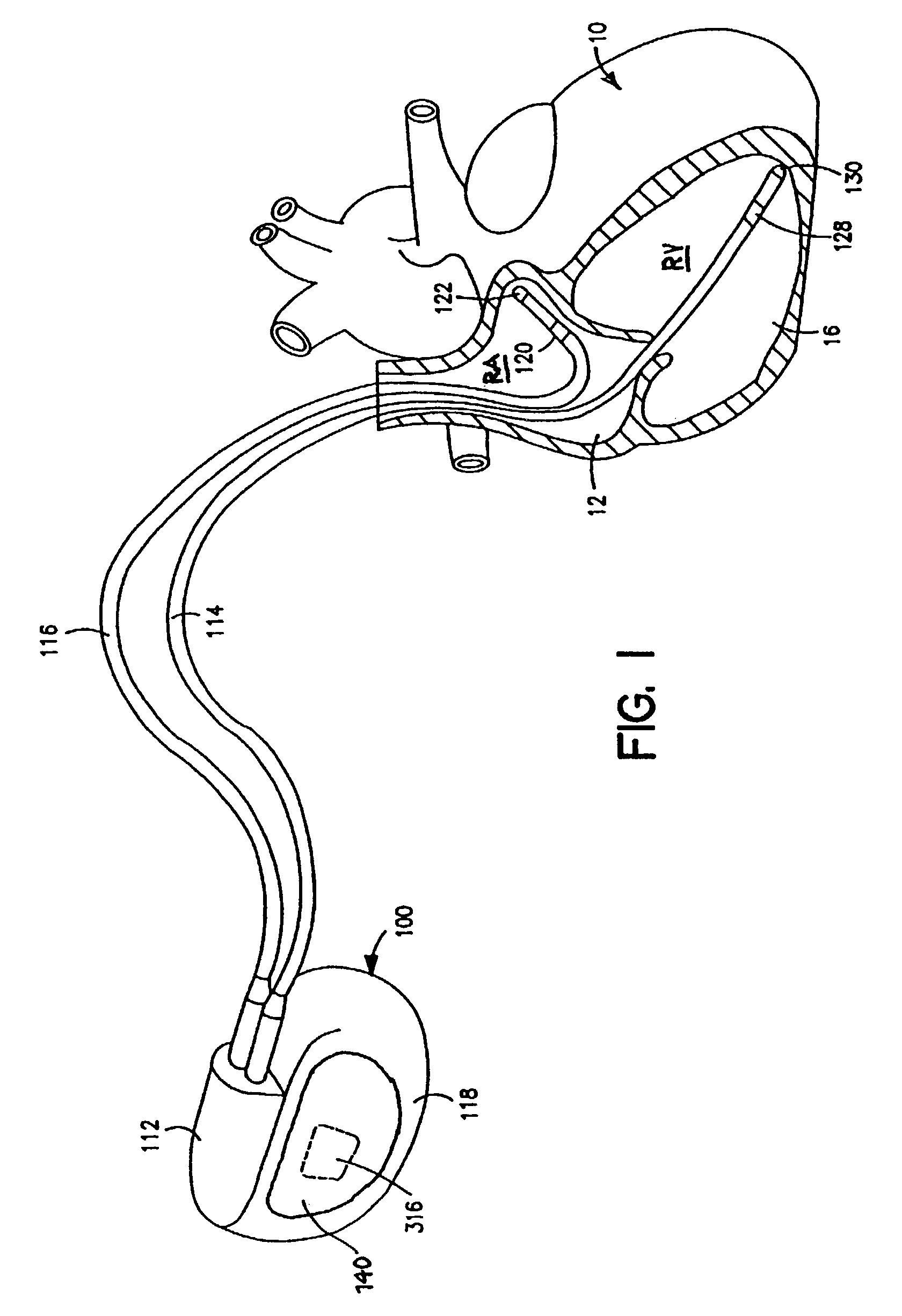
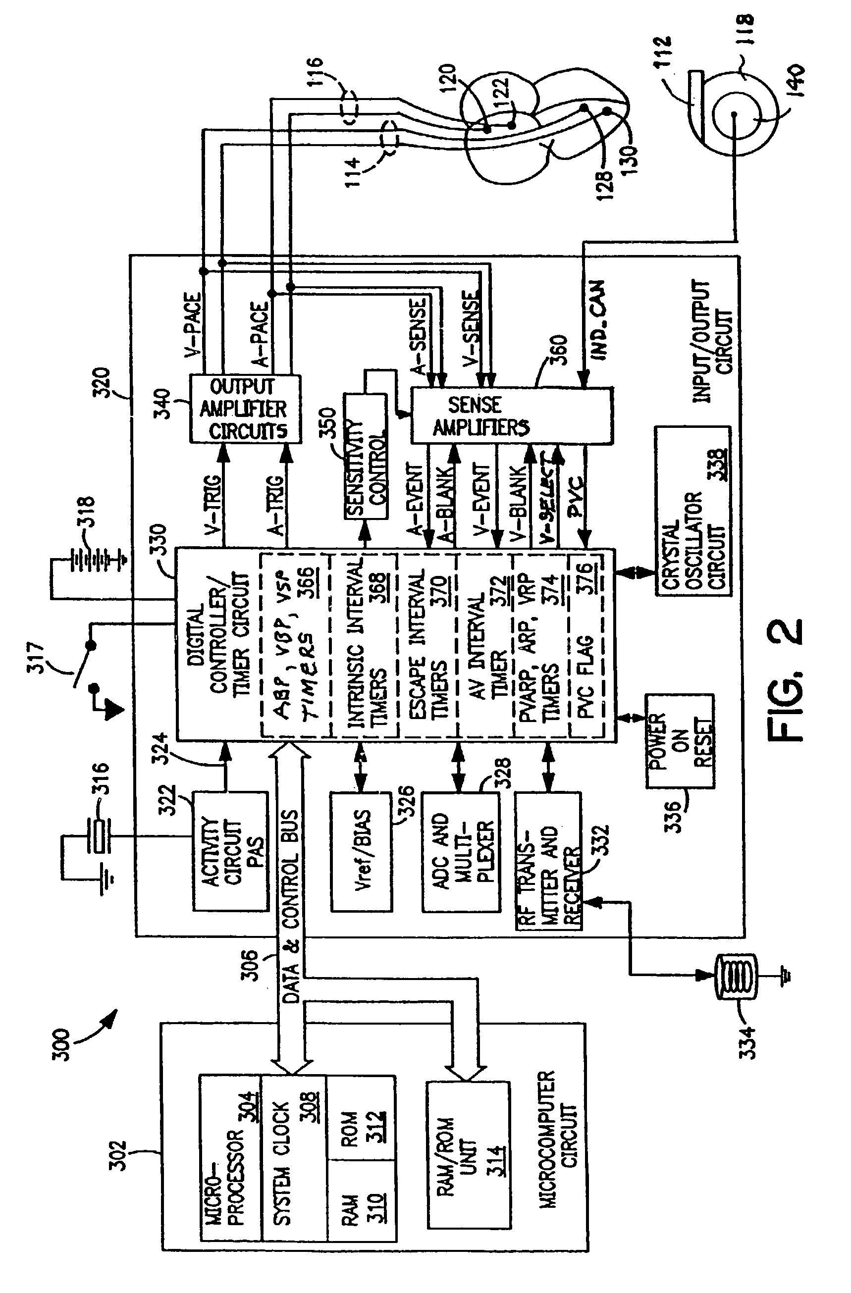
[0056]FIGS. 1 and 2 depict the external configuration and components of a typical implantable dual chamber pacemaker operating in a DDD, DDI, DDIR, or DDDR pacing mode or operating in an MI or MIR pacing mode to provide atrial pacing in the absence of an adequate atrial heart rate as long as ventricular sensing indicates normal AV conduction. Such a dual chamber IPG 100 and unipolar or bipolar atrial and ventricular leads 114 and 116 (bipolar leads are depicted), in which the present invention may be implemented is depicted in FIGS. 1 and 2. The dual chamber pacemaker IPG 100 senses and paces in the atrial and ventricular chambers, and pacing is either triggered and inhibited depending upon sensing of intrinsic, non-refractory atri...


PUM


Abstract

AV synchronous, dual chamber pacing systems are disclosed having improved sensing of ectopic ventricular depolarizations or PVCs coincidentally occurring at or shortly following delivery of an A-PACE pulse. A first ventricular sense amplifier that is blanked during and following delivery of an A-PACE pulse is coupled to active and indifferent ventricular pace / sense electrodes defining a ventricular sense vector for sensing natural ventricular depolarizations and declaring a V-EVENT. A far field PVC sense amplifier coupled to a far field PVC sense electrode pair defining a PVC sense vector detects such PVCs while the ventricular sense amplifier is blanked. A PVC declared during the ventricular blanking period by the far field PVC sense amplifier is employed to deliver a VSP pulse upon time-out of a VSP delay, if the VSP function is provided and programmed ON, and / or to halt time-out of an AV delay.

Description

RELATED APPLICATIONS[0001]This disclosure is related to the following co-pending U.S. patent application Ser. No. 11 / 260,984, filed Sep. 30, 2002, entitled “METHOD AND APPARATUS FOR PERFORMING STIMULATION THRESHOLD SEARCHES” by C. M. Manrodt et al., which is not admitted as prior art with respect to the present disclosure by its mention in this section.FIELD OF THE INVENTION[0002]This invention relates to implantable AV synchronous, dual chamber pacing systems, and particularly to improved sensing of ectopic ventricular depolarizations coincidentally occurring at or shortly following delivery of an atrial pacing pulse.BACKGROUND OF THE INVENTION[0003]Atrial synchronized, dual chamber, pacing modes, particularly, the multi-programmable, VDD, VDDR, DDD and DDDR pacing modes, have been widely adopted in implantable dual chamber pacemakers for providing atrial and ventricular or AV synchronized pacing on demand. Such dual chamber pacing modes have also been incorporated into implantable...

Claims


Application Information

Patent Timeline
IPC IPC(8): A61N1/362A61B5/364
CPCA61B5/0468A61N1/3622A61B5/364
Inventor SHELDON, TODD J.GILLBERG, JEFFREY M.
Owner MEDTRONIC INC
Learn More