Transmitter location for ultra-wideband, transmitted-reference CDMA communication system

a communication system and transmission reference technology, applied in the field of ultra-wideband (uwb) radio communication systems, can solve the problems of affecting the performance of such systems, affecting the location of sensitive communications equipment, and achieving the effect of more reliable and economical operation

Inactive Publication Date: 2009-03-03
GENERAL ELECTRIC CO
View PDF11 Cites 65 Cited by
  • Summary
  • Abstract
  • Description
  • Claims
  • Application Information

AI Technical Summary

Problems solved by technology

While narrowband and spread-spectrum systems have proven useful, they are not without drawbacks.
For example, the performance of such systems may be adversely affected by interference from strong local RF emitters.
The opposite is also true; i.e., because their transmitted energy is concentrated in a relatively limited spectrum, narrowband and conventional spread-spectrum systems may interfere with sensitive communications equipment located within or even external to the operating region.
Narrowband or spread-spectrum systems have also demonstrated poor performance in urban areas, or areas where there is a high concentration of electromagnetic interference.
For example, such transmissions are often unable to penetrate building components (e.g., walls, steel structures, elevator shafts, etc.), thereby making their use impracticable in many cases.
In addition, narrowband systems often require large power margins in order to combat significant frequency-selective fading, which is associated with indoor RF transmissions.
Because the location of the application described here is indoors, the range of values taken by the height of the transmitter off the floor is limited.
The use of extra bandwidth on the secondary wired network is a drawback, because it contributes substantially to the system cost.
Clock skew is easily introduced when the system clock is distributed with a cable.
This increases system cost and complicates installation as well as maintenance and repair of the system.

Method used


Image

  • Transmitter location for ultra-wideband, transmitted-reference CDMA communication system
  • Transmitter location for ultra-wideband, transmitted-reference CDMA communication system
  • Transmitter location for ultra-wideband, transmitted-reference CDMA communication system

Examples


Embodiment Construction

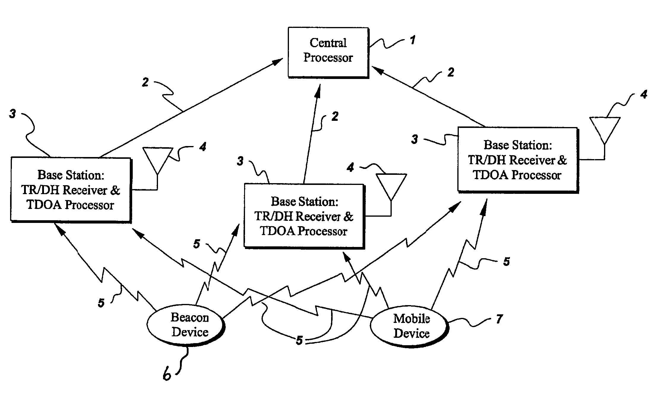
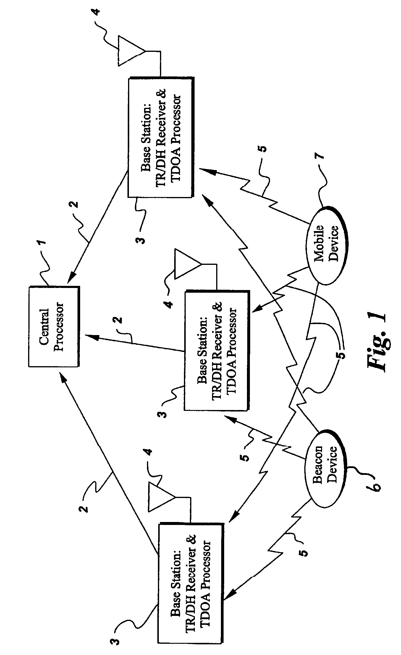
[0022]Referring to FIG. 1, an exemplary embodiment of a communications system of the present invention includes a central processor 1 which communicates via low-bandwidth communications channel 2 to at least three base stations 3. The base stations 3 are equipped with antennas 4 for receiving TR-UWB transmissions from one or more beacon devices 6 and / or one or more mobile devices 7, all of which are located within an area of interest. The area of interest may lie entirely within or include a medical facility, such as a hospital, to allow the base station 3 to track the location of medical assets and / or patients, and if desired to receive physiological data from those patients. While embodiments of the present invention are well suited for the hospital setting, those skilled in the art can appreciate that the area of interest may be any other area in which objects may be tracked or monitored, including day care centers for tracking children, warehouses for tracking inventory, mobile ...


PUM


Abstract

A system and method involve determining the location of objects within an area of interest using wireless signals. The system includes at least three base stations communicating with a central processor and a plurality of mobile devices. Further, at least one fixed beacon transmitter of known location may be provided. The mobile devices transmit a wireless signal to the base stations, which then determine a location of the mobile devices based on time difference of arrival information between the mobile devices measured at all the base stations.

Description

CROSS REFERENCE TO RELATED APPLICATIONS[0001]The subject matter of this application is related to non-provisional patent application Ser. No. 09 / 753,443 for “Ultra-Wideband Communication System”, assigned to the assignee of this application. This application is a continuation-in-part of U.S. patent application Ser. No. 09 / 973,140 filed Oct. 9, 2001 now U.S. Pat. No. 7,269,427, for “TRANSMITTER LOCATION FOR ULTRA-WIDEBAND, TRANSMITTED-REFERENCE CDMA COMMUNICATION SYSTEM,” which is hereby incorporated by reference herein in its entirety.STATEMENT REGARDING FEDERALLY SPONSORED RESEARCH & DEVELOPMENT[0002]The U.S. Government may have certain rights in this invention pursuant to the National Institute of Standards and Technology Contract Number 70ANB0H3035 awarded by NIST.BACKGROUND OF THE INVENTION[0003]Various embodiments of the present invention relate to the use of ultra-wideband (UWB) radio communication systems. In particular, the various embodiments pertain to a transmitted-refere...

Claims


Application Information

Patent Timeline
Patent Type & Authority Patents(United States)
IPC IPC(8): H04B7/00H04M1/00H04M11/04G01S5/06H04B1/7163H04Q7/20H04Q7/34H04Q7/38
CPCG01S5/06H04B1/7163
Inventor HOCTOR, RALPH THOMASHERSHEY, JOHN ERIKVAN STRALEN, NICK ANDREWTOMLINSON, JR., HAROLD WOODRUFF
Owner GENERAL ELECTRIC CO
Why Eureka
Try Eureka