Self-clearing strainer for fluid intake

a strainer and fluid technology, applied in the field of fluids, can solve problems such as loss of life and property

Inactive Publication Date: 2009-03-10
LAWRENCE SR JOSEPH W
View PDF12 Cites 23 Cited by
  • Summary
  • Abstract
  • Description
  • Claims
  • Application Information

AI Technical Summary

Problems solved by technology

In relation to his duties as a volunteer fire-fighter, Applicant has often experienced clogging of a suction hose placed in a lake or stream intended to enable a pumper truck to utilize riparian water to combat a blaze.
In fire fighting, time is of the essence and any delays can result in loss of property and, in some cases, loss of lives.

Method used


Image

  • Self-clearing strainer for fluid intake
  • Self-clearing strainer for fluid intake
  • Self-clearing strainer for fluid intake

Examples


first embodiment

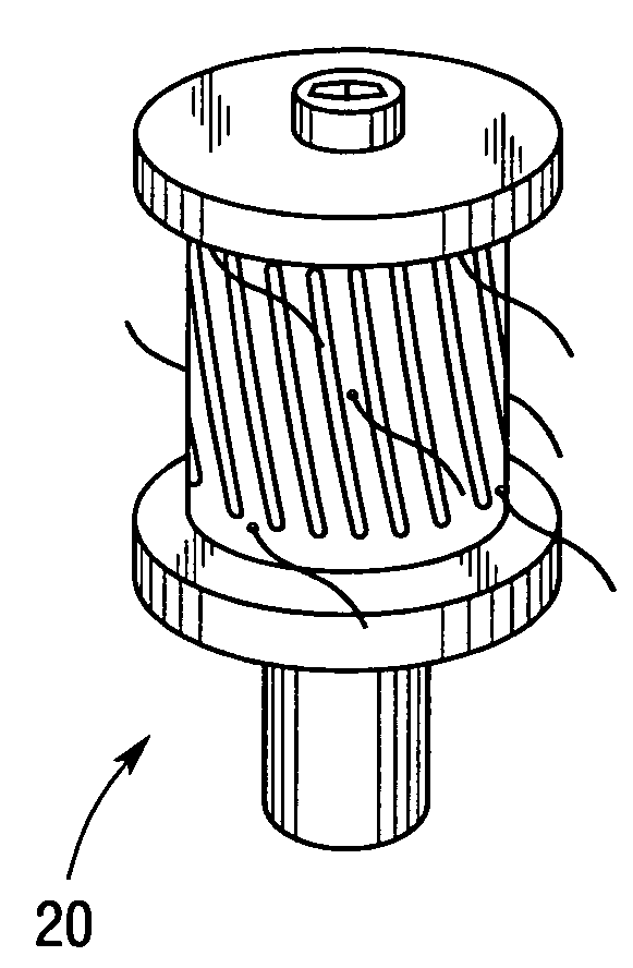
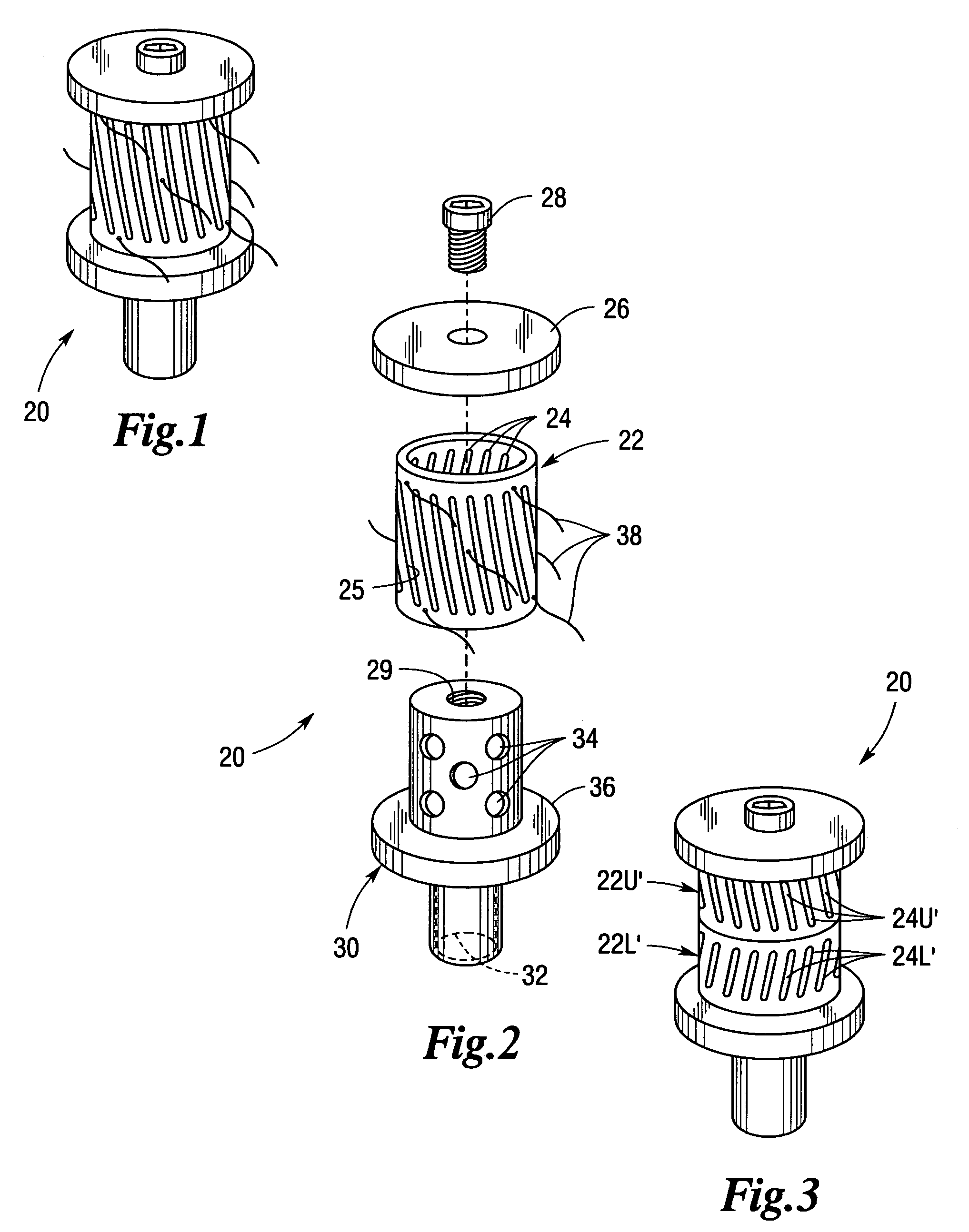
[0012]the self-clearing strainer of the present invention is depicted in FIGS. 1 and 2 generally at 20. Cylindrical tumbler 22 has a plurality of angled slots 24 cut through its peripheral wall and is mounted on an intake plug 30 that fits in the end of an intake hose (not shown). Intake plug 30 has a throughbore 32, a plurality of laterally extending holes 34 which intersect throughbore 32 and a radial flange or base 36. Cylindrical tumbler 22 is retained in place by a cap 26 and retainer screw 28. The distance between the base 36 of intake plug 30 and cap 26 exceeds the length of the cylindrical tumbler 22 enabling it to turn freely thereon. The leading edge 25 of each slot 24 functions as a vane. When suction is applied to the hose, cylindrical tumbler 22 rotates at a significant rate of speed resisting clogging by throwing any debris out away from its peripheral surface. Depicted in FIGS. 1 and 2 are a plurality of flexible strands 28 (e.g., fishing line) which further serve to ...

second embodiment

[0013]A second embodiment is depicted in FIG. 3 generally at 20′. Strainer 20′ includes two tumblers 22U′ and 22L′ that are mounted coaxially with slots 24U′ and 24L′ slanting in opposite directions such that the tumblers rotate in opposed directions. Although not shown, it will be appreciated that a flange between the two tumblers 22U′ and 22L′ will facilitate their respective rotations. The turbulence induced by such counter rotation further helps to maintain clog-free operation.

third embodiment

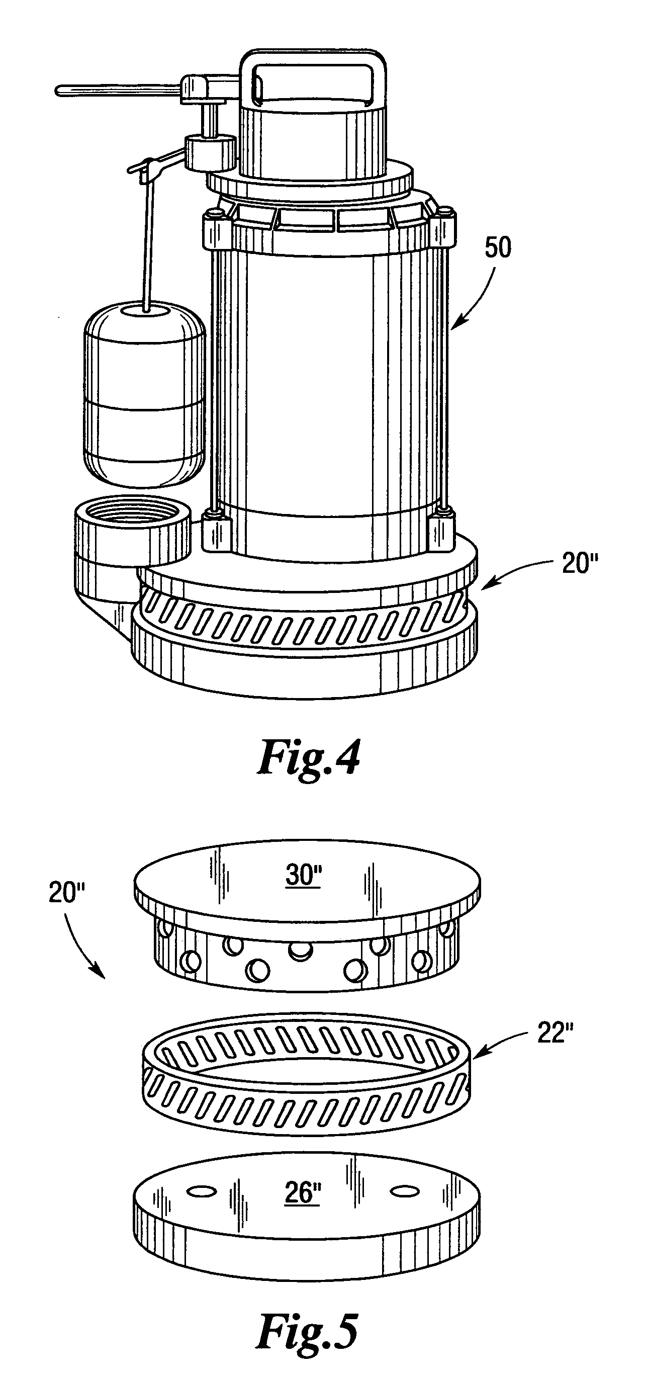
[0014]the present invention is depicted in FIG. 4 generally at 20″. In this embodiment, self-clearing strainer 20″ is assembled on sump pump 50. As shown in FIG. 5 in an exploded view, the diameters of cylindrical tumbler 22″, cap 26″ (which, in this inverted application, lies beneath tumbler 22″) and plug 30″ are adjusted to provide a diameter consistent with that of the base 52 of the sump pump 50. As the sump pulls suction through angled slots 24″, leading surfaces 25″ form impeller vanes causing tumbler 22″ to spin throwing off accumulated debris, thereby self-clearing strainer 20″.

[0015]As seen in FIG. 6, a floating strainer 60 can be positioned to receive the strainer 20 of the present invention around an external portion of housing 64 which is suspended below a pair of floats 62, should the water conditions suggest that water would more preferably be drawn from near the surface. The self-clearing strainer 20 when attached to a plug 30 in the end of a hose, would normally sink...


PUM

PropertyMeasurementUnit
lengthsaaaaaaaaaa
flexibleaaaaaaaaaa
lengthaaaaaaaaaa

Abstract

A cylindrical tumbler has a plurality of angled slots positioned about its periphery, the leading edge face of each slot forming an angled impeller vane. When the tumbler is placed on an intake plug and suction applied through the plug, the tumbler spins throwing off any debris which may otherwise accumulate on the strainer. In alternate embodiments, lengths of flexible strand can be attached to the periphery of the tumbler or two tumblers with oppositely angled slots, and hence, opposite spin directions can be positioned on the same plug to increase turbulence and further reduce debris accumulation.

Description

[0001]Applicant claims the benefit of provisional patent appl. No. 60 / 928,763 filed May 11, 2007.BACKGROUND AND SUMMARY OF THE INVENTION[0002]The present invention is directed to the field of fluids. More particularly, the present invention is directed to a strainer for a fluid intake which is self-clearing.[0003]The application which gave rise to the present invention relates to fire-fighting. In relation to his duties as a volunteer fire-fighter, Applicant has often experienced clogging of a suction hose placed in a lake or stream intended to enable a pumper truck to utilize riparian water to combat a blaze. In fire fighting, time is of the essence and any delays can result in loss of property and, in some cases, loss of lives. The present invention was developed to cope with the problem or clogged fire hoses. However, it is envisioned that the self-clearing strainer of the present invention has a much broader application including, but not limited to, use with sump pumps, and the...

Claims


Application Information

Patent Timeline
Patent Type & Authority Patents(United States)
IPC IPC(8): B01D35/10B01D33/067B01D33/29B01D33/56B01D35/26
CPCB01D29/33B01D33/067B01D35/02B01D29/54B01D29/74B01D33/073B01D33/39B01D33/56B01D35/26
Inventor LAWRENCE, SR., JOSEPH W.
Owner LAWRENCE SR JOSEPH W
Why Eureka
Try Eureka