
Wellbore filter for submersible motor-driver pump

a technology of submersible motors and filters, applied in the field of geophysical methods of well survey, can solve the problems of idling of wells, high cost of above-mentioned well cleanup technologies, and significant erosion of impellers and diffusers, and achieve the effect of prolonging the service life of submersible motor-driven pumps

Inactive Publication Date: 2008-05-15
SCHLUMBERGER TECH CORP
View PDF2 Cites 20 Cited by
  • Summary
  • Abstract
  • Description
  • Claims
  • Application Information

AI Technical Summary

Benefits of technology

[0020]The implementation of a new design of a wellbore filter makes the service life of submersible motor-driven pump longer.

Problems solved by technology

Since the fluid velocity in the pump system is rather high, these particles could cause a significant erosion of impellers and diffusers.
The above-mentioned well cleanup technologies are expensive and require idling of the well (while the flexible coil tubing is in operation or submersible motor-driven pump is being replaced).
Electric submersible pumps are known to be damaged by small-sized particles in the course of operation.
These damages limit the service life of submersible motor-driven pump and the pump should be replaced.
The pump replacement procedure is rather expensive and required idling of the well (at least for a period when works in the well are performed).
A typical issue that arises due to the filter operation is clogging after a certain period of operation; the filter clogging results in a reduced throughput or in a fully obstructed flow.
This issue emerges after the formation fracturing.
It is a challenging to handle that amount of solid particles.
A sophisticated structural design and a lack of packing between the filter housing and the wellbore walls are the disadvantages of this filter design.
The rigid structure of the sealing element creates problems with lowering the strainer to the well and may cause the damage of the said strainer.
This damage creates leakage in the top part of the strainer.

Method used


Image

  • Wellbore filter for submersible motor-driver pump
  • Wellbore filter for submersible motor-driver pump
  • Wellbore filter for submersible motor-driver pump

Examples


Embodiment Construction

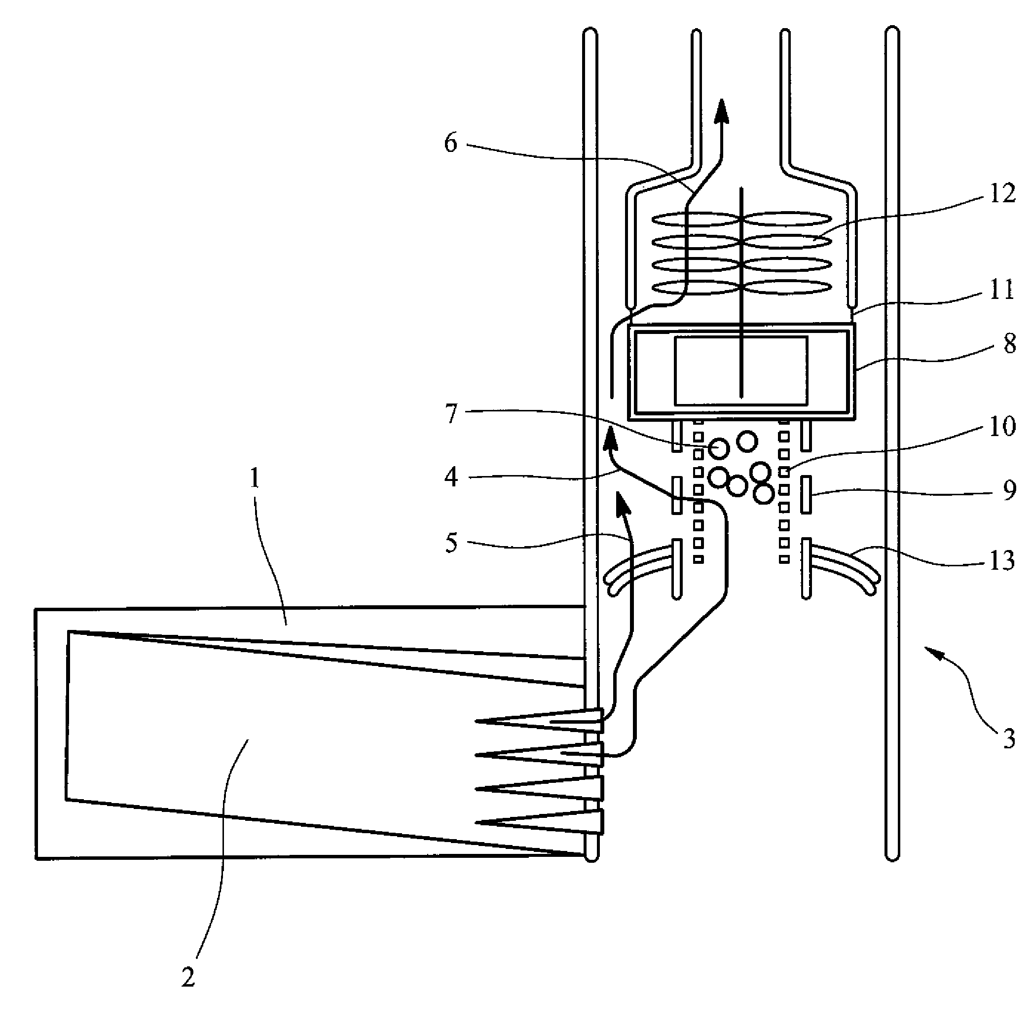
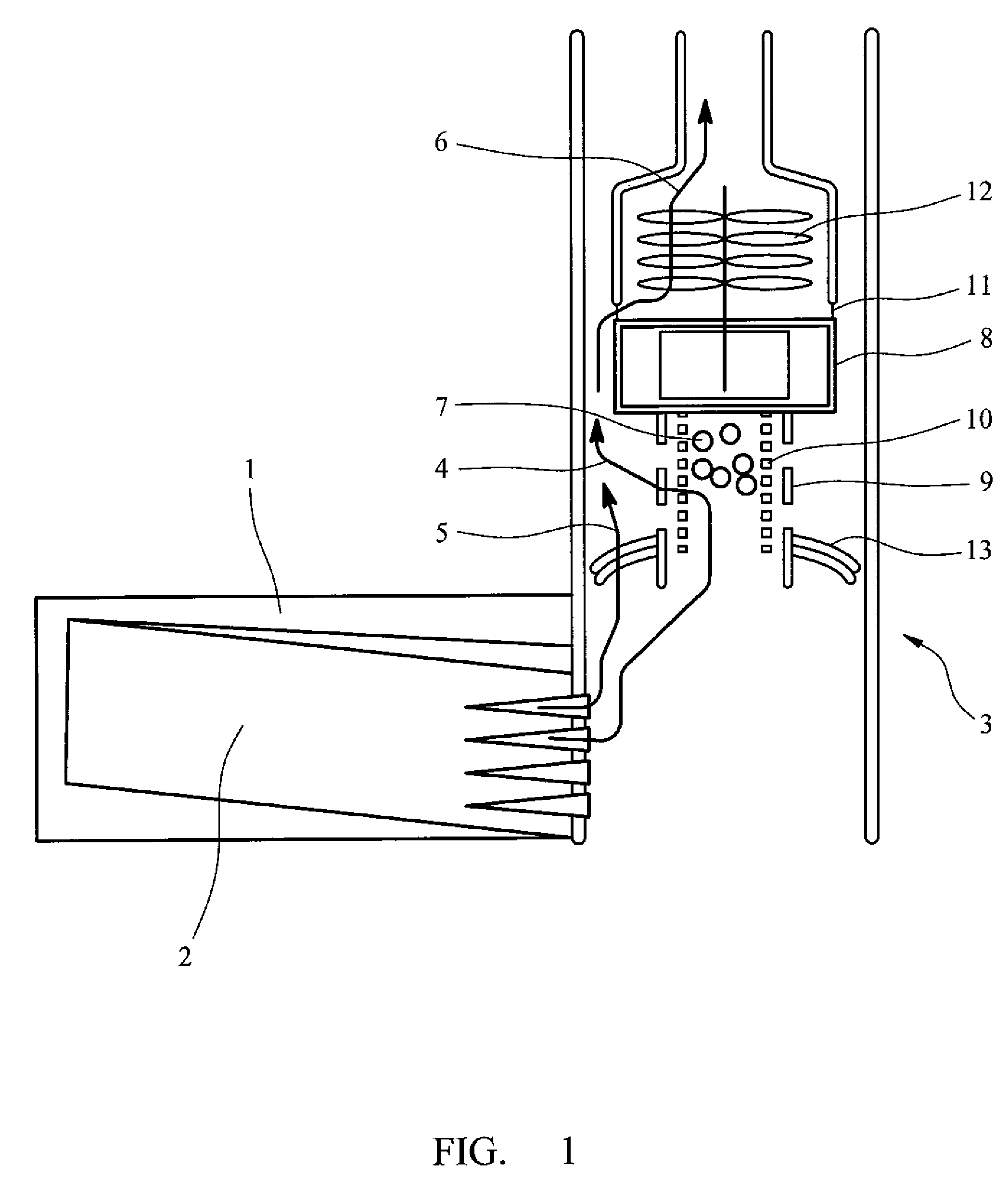
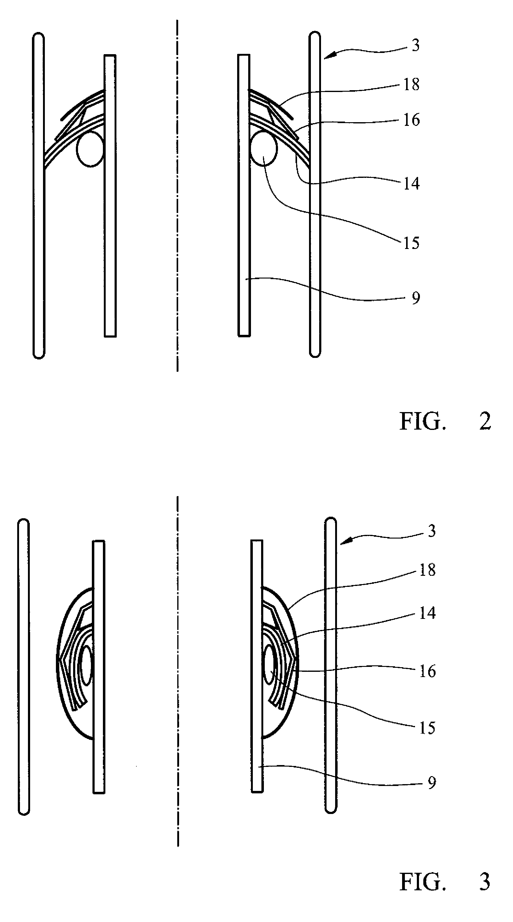
[0023]These illustrative figures have the following notions: formation 1, fracture 2, casing 3, initial direction of flow 4, direction of flow after collapsible sealing element is broken 5, flow through the submersible pump 6, solid particles 7, pump motor 8, filter housing 9, filtering element 10, intake port 11, section of pump 12, sealing element 13, rubber cup 14, expanding ring 15, elastic energizing element 16, inflatable rubber packer 17, protective sheath 18, thin rubber layer 19, armored elastic layer 20, remains of broken armored layer 21, pressure feeding line 22, accumulating chamber for liquid 23, bypass tube 24, port 25, filtering volume 26, outside surface of filter 27, temporary plug 28.

[0024]The disclosed filter design intended for furnishing submersible motor-driven pumps by attaching the said filter to the bottom section of the mechanical structure of the submersible motor-driven pump. The filter housing 9 is an elongated cylinder. Since the diameter of the filter...


PUM


Abstract

This invention related to the geophysics, in particular, to geophysical methods of well survey, and can be applied for removal of wellbore liquid that fill the well, during the well logging process. This invention characterizes a filter for solid particles; which can be mounted at the suction side of submersible motor-driven pumps.A well filter for submersible motor-driven pump comprising an elongated housing in which a cylindrical filtering element is installed. At one end of the filtering element, a fixture for fastening the filter housing to the pump is mounted; at the other end, there is at least one fluid intake port. A shape-deformable sealing element is installed on the housing outer surface.The rigid structure of the sealing element creates problems with lowering the strainer to the well and may cause the damage of the said strainer. This damage creates leakage in the top part of the strainer. The way of resolving the engineering issue is development of a new design of the wellbore filter. The implementation of a new design of a wellbore filter makes the service life of submersible motor-driven pump longer.

Description

TECHNICAL FIELD[0001]This invention related to the geophysics, in particular, to geophysical methods of well survey, and can be applied for removal of wellbore liquid that fill the well, during the well logging process.[0002]This invention characterizes a filter for solid particles; which can be mounted at the suction side of submersible motor-driven pumps. The formation fluid first passes through the filter and than goes to the submersible motor-driven pump. The design of this wellbore filter allows capturing of large-sized solid particles, e.g., proppant particles (following the formation fracturing process) and / or debris that remained in place after perforation job. This filter is featured by a limited volume of accumulating particles; however, once the throughput capacity for fluids is exhausted, the filter in concern can be used for operation in a bypass mode. In this case, fluids to be removed bypass the filter and enter the suction hole of the submersible motor-driven pump.[...

Claims


Application Information

Patent Timeline
IPC IPC(8): E21B33/126
CPCE21B43/128E21B21/002E21B33/126
Inventor ORBAN, JACQUES
Owner SCHLUMBERGER TECH CORP
Learn More