Method for Attaching a Blower Unit to Industrial Equipment and Apparatus Used Therewith and Methods for Using the Same

a blower unit and industrial equipment technology, applied in the direction of machines/engines, waterborne vessels, metal-working apparatuses, etc., can solve the problems of limiting the excavating machine, significant amount of dust and other small particles is generated and introduced into the surrounding air, and significant amount of dust and debris is created at or around the point of impact with the ground

Inactive Publication Date: 2009-07-02
DUST CONTROL TECH
View PDF27 Cites 18 Cited by
  • Summary
  • Abstract
  • Description
  • Claims
  • Application Information

AI Technical Summary

Benefits of technology

[0004]One aspect of the invention method encompasses a method comprising providing a blower unit comprising a base with a frame extending upward from the base and a fan propelled mister attached to the frame, wherein the fan propelled mister comprises a fan for drawing air into the fan propelled mister, a discharge tube for creating a high velocity airflow exiting from a distal end of the discharge tube, and a plurality of nozzles operatively connected to a fluid intake and located proximate the distal end of the discharge tube for creating a mist when placed in communication with a fluid source. In accordance with the method, a heavy industry, rigid frame, mobile, engine-powered machine is provided. The machine has a lift arm selectively vertically positionable between raised and lowered positions. The lift arm has an implement on its distal end adapted for remote operation by an operator of the machine, and a mount spaced from

Problems solved by technology

During a variety of work, including but not limited to, construction or demolition work or at coal powered power plants, steel mills, foundries, and other basic industries, a significant amount of dust and other small particles and contaminates is generated and introduced into the surrounding air.
Furthermore, when using large machinery such as a backhoe or other excavating equipment, a significant amount of dust and debris is created at or around the point of impact with the ground.
However, i

Method used


Image

  • Method for Attaching a Blower Unit to Industrial Equipment and Apparatus Used Therewith and Methods for Using the Same
  • Method for Attaching a Blower Unit to Industrial Equipment and Apparatus Used Therewith and Methods for Using the Same
  • Method for Attaching a Blower Unit to Industrial Equipment and Apparatus Used Therewith and Methods for Using the Same

Examples


Embodiment Construction

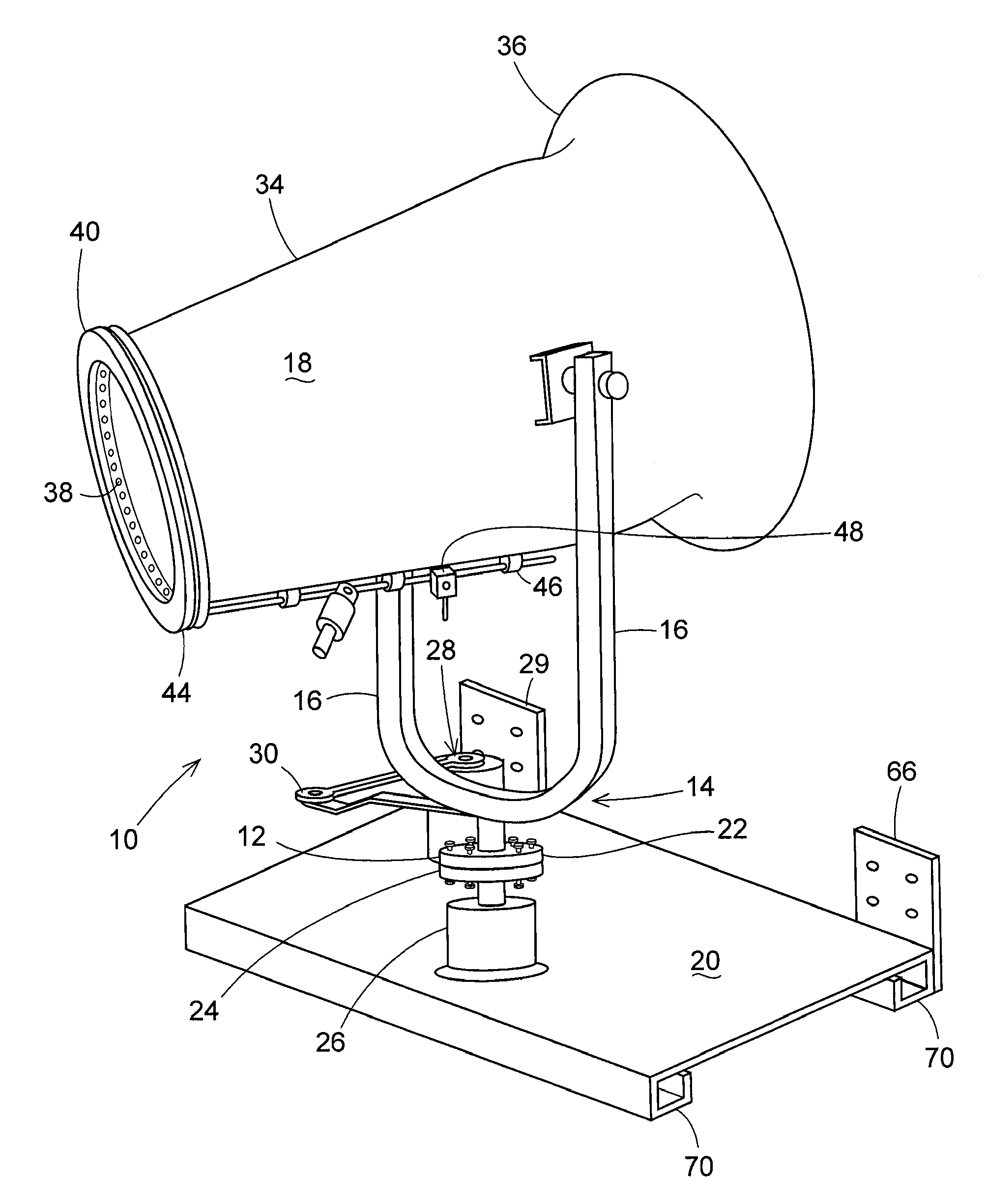
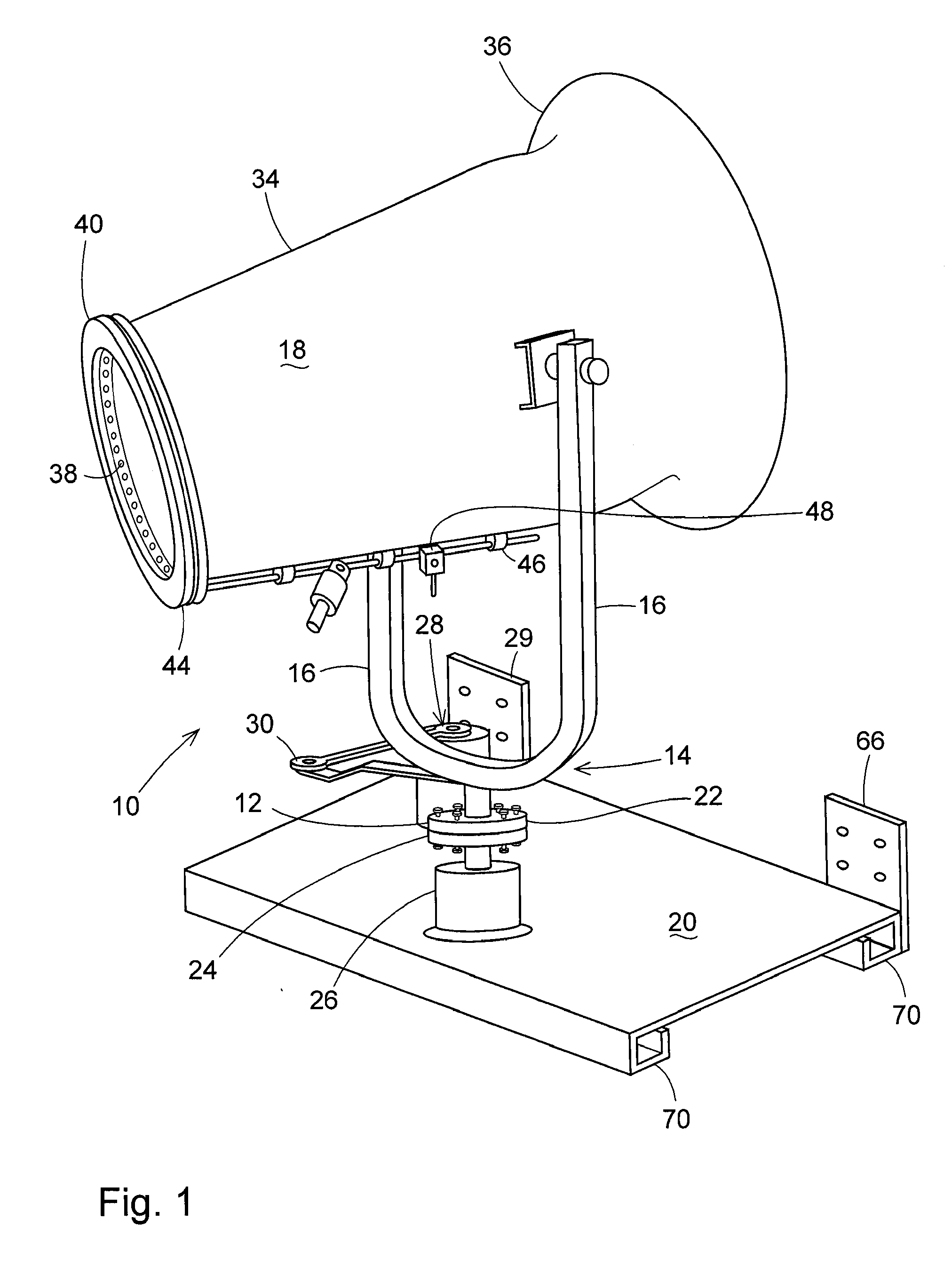
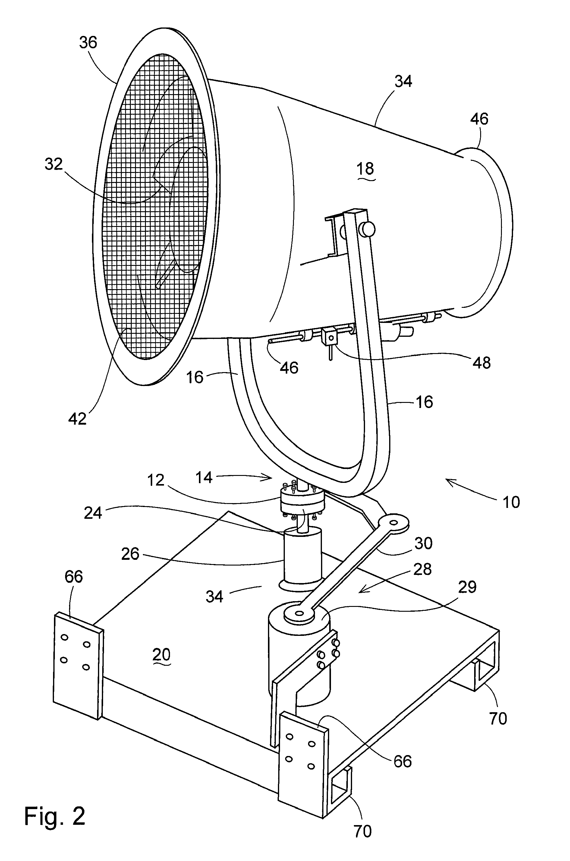
[0016]Referring to the accompanying drawings in which like reference numbers indicate like elements, FIGS. 1 and 2 illustrate the general arrangement of the blower unit 20. The blower unit 10 has a base 12 with a frame 14 comprising two arms 16 that extend upward from the base for supporting a fan propelled mister 18 therebetween. The blower unit is supported on an attachment member 20 which is a generally rectangular planar support plate with sufficient rigidity to support the fan propelled mister 18. The base 12 has a coupling portion 22 that secures the base to a connector 24 of a bearing housing 26 that projects from the attachment member to enable oscillation of the base and frame about the attachment member.

[0017]The blower unit may have a base drive 28 to provide oscillatory movement of the fan propelled mister (left and right movement in FIGS. 1 and 2). The frame may have actuators located in the arms (not shown) to provide rotary movement of the fan propelled mister (up and...


PUM

PropertyMeasurementUnit
Angleaaaaaaaaaa

Abstract

A blower unit has a base, a frame extending upward from the base and a fan propelled mister attached to the frame. The fan propelled mister comprises a fan, a discharge tube, and a plurality of nozzles operatively connected to a fluid intake for creating a mist. A rigid frame, mobile engine-powered machine having a lift arm with a mount is provided. An attachment is also provided having a first surface with a coupling portion adapted to secure the attachment to the mount on the lift arm and a second surface with a coupling portion adapted to secure the attachment to the base. The attachment is mounted to the lift arm with the first coupling portion of the first surface, and to the base with the second coupling portion of the second mounting surface. The blower unit and attachment and methods of use of the same are described.

Description

BACKGROUND[0001]This invention relates generally to methods of attaching a blower unit to industrial equipment, such as construction equipment, and, fixtures used therewith. The disclosure also discussed methods of use of industrial equipment equipped with such a blower unit.[0002]During a variety of work, including but not limited to, construction or demolition work or at coal powered power plants, steel mills, foundries, and other basic industries, a significant amount of dust and other small particles and contaminates is generated and introduced into the surrounding air. Furthermore, when using large machinery such as a backhoe or other excavating equipment, a significant amount of dust and debris is created at or around the point of impact with the ground. Generally speaking, where there is dust, smoke or other contaminants in the air, it is also common for there to be odors. In order to provide a safe working environment as well as inhibit any damage done to the equipment or st...

Claims


Application Information

Patent Timeline
IPC IPC(8): B05B17/04B23P19/04F04D29/00
CPCF04D29/601Y10T29/53F04D29/705
Inventor PETERSON, EDWIN
Owner DUST CONTROL TECH
Why Eureka
Try Eureka