Bow sight with sighting aperture

a sighting aperture and bow technology, applied in the field of sightings for bows, can solve the problems of poor eyesight and inability to readily indicate bow torque, and achieve the effect of improving shooting accuracy and increasing the visibility of the sighting apertur

Inactive Publication Date: 2009-03-17
AFSHARI ABBAS BEN
View PDF96 Cites 32 Cited by
  • Summary
  • Abstract
  • Description
  • Claims
  • Application Information

AI Technical Summary

Benefits of technology

[0014]In another embodiment, a plurality of fiber optic members, each having a terminal end are disposed around the sighting aperture to increase the visibility of the sighting aperture.
[0015]Each of the fiber optic members of the first sighting structure may be supported by a strut that extends between the pin guard and the sight aperture. In addition, these struts may form a “cross-hair” configuration within the sight window of the pin guard for better shooting accuracy.
[0020]In yet another embodiment, a plurality of second sighting structures is provided with each having a sight point positioned at a different height when viewed in a shooting position. The vertical adjustability of the sight points allows for visual alignment of the first sighting structure with one of the second sighting structures for shooting at different distances-to-target. Each of the second sighting structures may be independently and selectively adjustable relative to the first sighting structure.

Problems solved by technology

In addition, such sights do not readily indicate bow torque that will otherwise cause an archer to shoot to the left or right of the target if a transverse torque is applied between the riser and string when shooting.
Moreover, multiple pin prior art bow sights require the archer to quickly select the appropriate sight pin to aim at the target that may be difficult for archers with poor eyesight and / or in low light conditions.

Method used


Image

  • Bow sight with sighting aperture
  • Bow sight with sighting aperture
  • Bow sight with sighting aperture

Examples


Embodiment Construction

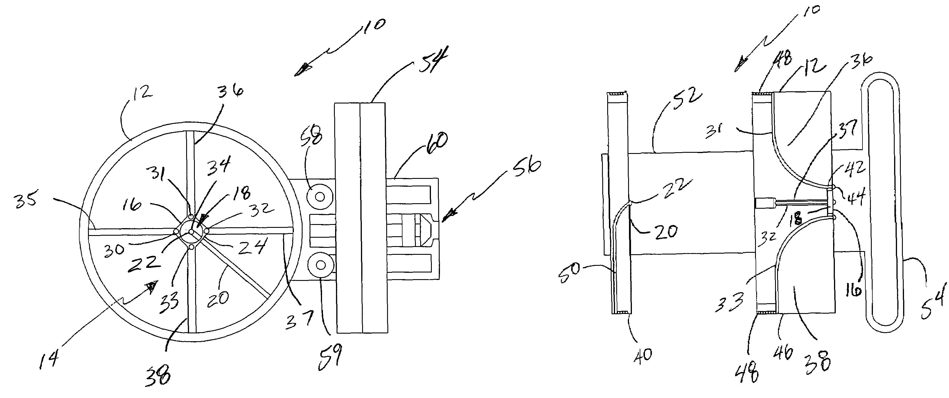
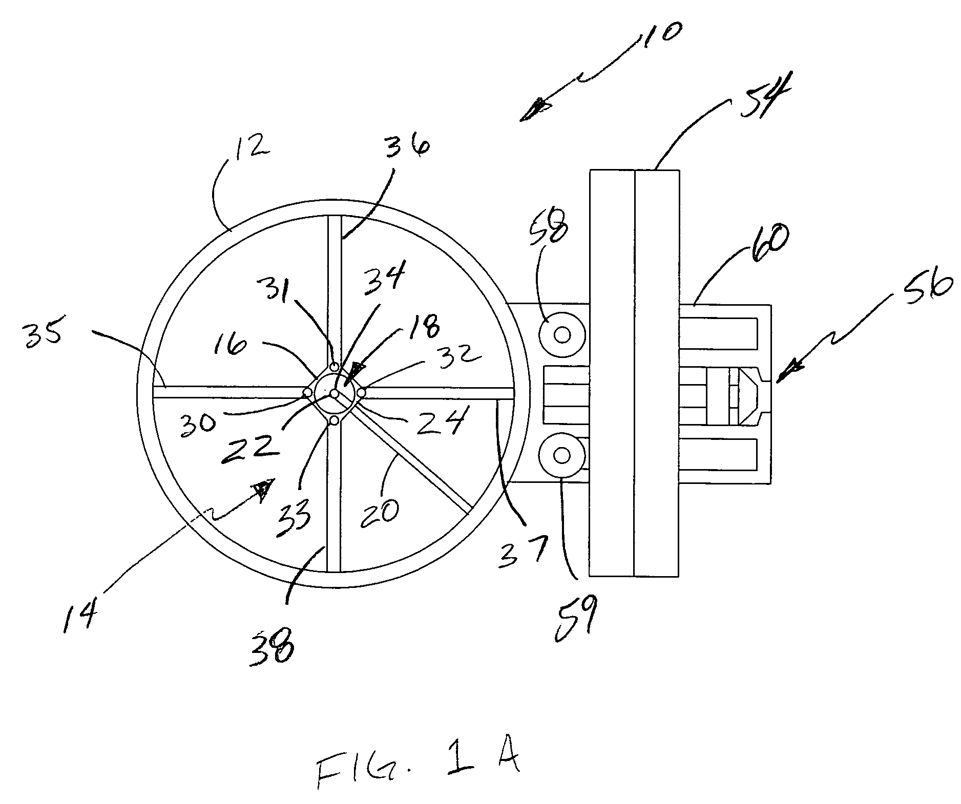
[0041]FIG. 1A illustrates a bow sight, generally indicated at 10 in accordance with the principles of the present invention. The sight 10 is comprised of a pin guard 12 defining a sight window 14. A first sighting structure 16 is coupled to the pin guard 12. The first sighting structure defines a sighting aperture 18 positioned within the sight window 14. The first sighting structure 16 could be used alone in the form of an effective “hollow sight pin” when used in conjunction with a conventional peep sight for example. Thus rather than having a sight point or sight tip, as with a traditional bow sight, the sight point is replaced by a sight aperture that is positioned over a target with the center of the target positioned proximate the center of the sight aperture when aiming. Such a sight aperture 18 is particularly useful when the archer does not necessarily have sharp vision, as for example, with older persons. The sight aperture provides a larger sighting indicia for the archer...


PUM


Abstract

A bow sight is comprised of a first sighting structure defining a sighting aperture and a second sighting structure defining a sight point. The first sighting structure is positioned in front of the second sighting structure with the sight point of the second sighting structure being visible within the sighting aperture of the first sighting structure.

Description

BACKGROUND OF THE INVENTION[0001]1. Field of the Invention[0002]This invention relates generally to sights for archery bows and, more specifically, to bow sights having multiple sighting structures that can be visually aligned to provide more accurate shooting.[0003]2. Description of the Art[0004]Archery bow sights utilizing a plurality of sight pins have been known in the art for many years. Typically, these sights use a bracket or other mounting structure for mounting the sight to a bow. The sight is commonly comprised of a pin plate, a pin guard, and a plurality of sight pins which are secured to the pin plate and extend into a sight window formed by the pin guard. The sight is mounted to a bow in a manner so that when the bow string is drawn, the archer can look through a peep sight provided in the bow string and align the tip of a pin attached to the sight with a target. For sights utilizing a plurality of horizontally extending sight pins having their tips vertically aligned, ...

Claims


Application Information

Patent Timeline
Patent Type & Authority Patents(United States)
IPC IPC(8): F41G1/467
CPCF41G1/467
Inventor AFSHARI, ABBAS BEN
Owner AFSHARI ABBAS BEN
Why Eureka
Try Eureka