Image display device and method of displaying image

a display device and image technology, applied in the field of image display devices and a display method, can solve the problems of flicker caused by impulse-type display, image perception of out-of-focus, and waste of power consumed by the backlight which is continuously turned on during black display

Inactive Publication Date: 2009-03-17
KK TOSHIBA
View PDF15 Cites 45 Cited by
  • Summary
  • Abstract
  • Description
  • Claims
  • Application Information

AI Technical Summary

Problems solved by technology

However, the liquid crystal display devices or the organic EL display devices have a problem such that images are percieved to be out-of-focus when moving images are displayed.
This problem is caused by the fact that time-axis characteristics in method of displaying image are different between the liquid crystal display device or the organic EL display device and the CRT.
However, a power consumed by a backlight which is continuously turned on during black display is wasted.
Also, in the case of the still image, there arises such problem that flicker which is caused by the impulse-type display may occur.
However, in the above-described method, for example, black is displayed in the same manner for the moving image with small motion and for the moving image with large motion, sufficient effect for reducing power consumption cannot be expected.
Although the criteria between the moving image and the still image may be set to a value rather closer to the moving image in order to increase the effect for reducing power consumption, the quality of the moving image is deteriorated in this case.
In addition, the abrupt change in a black display time ratio (black display period / one frame period) such as the change-over between the impulse display and the hold display are recognized as the flicker by the observers, which may result in deterioration of the image quality.

Method used


Image

  • Image display device and method of displaying image
  • Image display device and method of displaying image
  • Image display device and method of displaying image

Examples


first embodiment

[0042]Referring now to FIG. 1 to FIG. 12, a liquid crystal display device 10 according to a first embodiment of the invention will be described.

(1) Structure of the Liquid Crystal Display Device 10

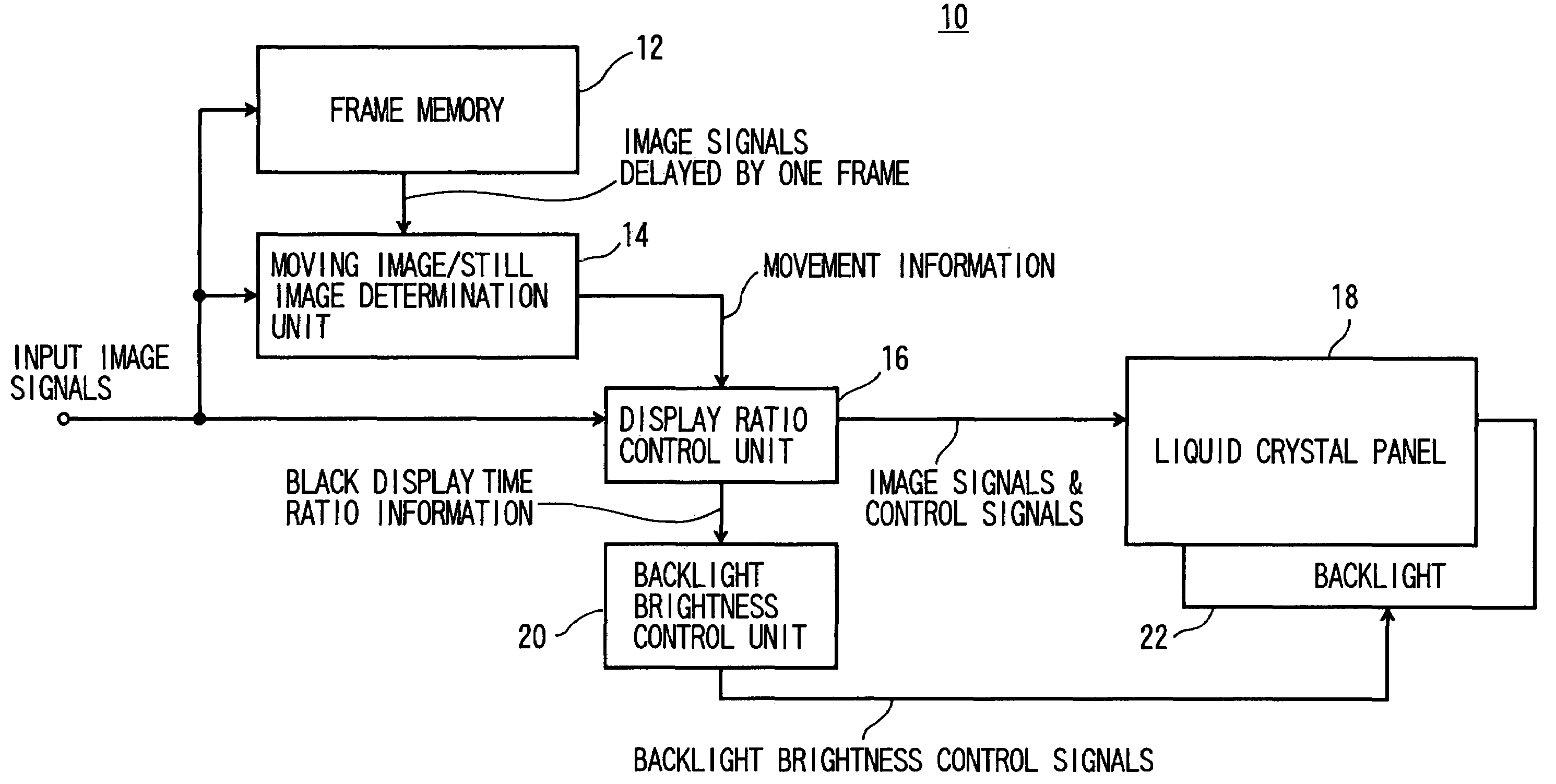
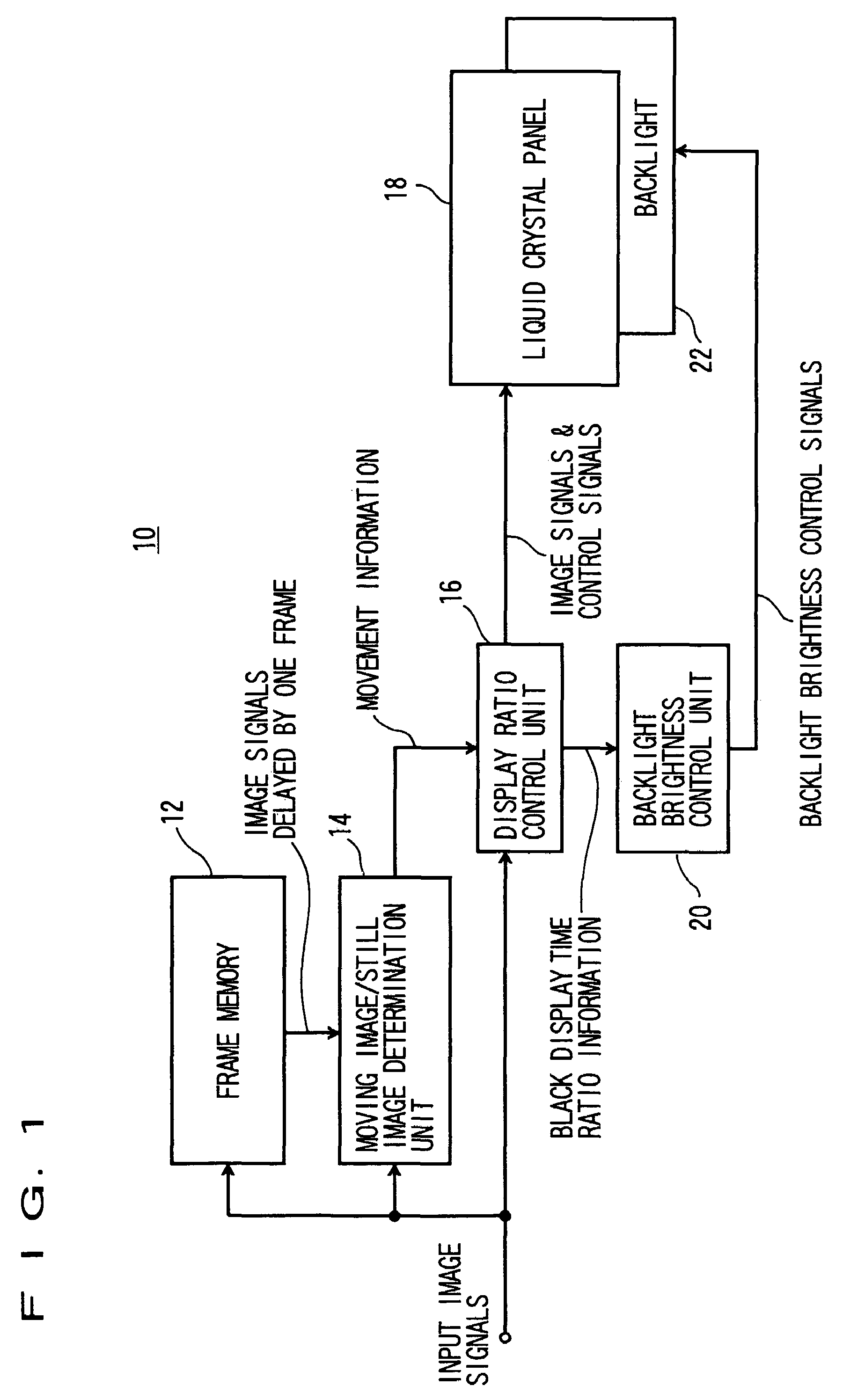
[0043]The structure of the liquid crystal display device 10 according to the first embodiment of the invention will be described in FIG. 1.

[0044]The input image signal is inputted to a frame memory 12, a moving image / still image determination unit 14, and a display ratio control unit 16.

[0045]The frame memory 12 holds input image signals for one frame period, and outputs the same to the moving image / still image determination unit 14 as the image signals delayed by one frame. The term “one frame” used herein represents one image which is displayed on the liquid crystal display device 10, and hence one field which is generally referred in relation to interlaced image signals and one frame used herein represent the identical meaning.

[0046]The moving image / still image determination unit 14 det...

second embodiment

[0125]Referring to FIG. 13 and FIG. 14, the liquid crystal device 10 according to a second embodiment of the invention will be described.

(1) Structure of Liquid Crystal Display Device 10

[0126]FIG. 13 shows a structure of the liquid crystal display device 10 according to the second embodiment of the invention.

[0127]Although the basic structure of the liquid crystal display device 10 according to the second embodiment is the same as the first embodiment, the second embodiment is characterized in that movement information which is more detailed than the moving image / still images is detected from the input image by a movement detection unit 24, and the black display time ratio which is divided into smaller sections is controlled.

(2) Movement Detection Unit 24

(2-1) Structure of the Movement Detection Unit 24

[0128]The movement detection unit 24 detects the movement by using a plurality of frames of the input image signals, and outputs the same as movement information. In this embodiment, ...

third embodiment

[0171]Referring now to FIG. 15, the liquid crystal display device 10 according to a third embodiment will be described.

(1) Structure of the Liquid Crystal Display Device 10

[0172]FIG. 15 shows a structure of the liquid crystal display device 10 according to the third embodiment of the invention.

[0173]Although the basic structure of the liquid crystal display device 10 according to the third embodiment is the same as the first embodiment, the third embodiment is characterized in that the average gray-scale level of the input image is calculated to control the amount of change in the transient black display time ratio using the detected result.

(2) An Average Gray-scale Level Detection Unit 26

[0174]The average gray-scale level detection unit 26 detects the average gray-scale level of the input image. Assuming that X represents the number of pixels in the horizontal direction and Y represents the number of pixels in the vertical direction in the Nth frame, the average gray-scale level Ga...


PUM


Abstract

It is an object of the invention to provide an image display device for improving the image quality of moving images and still images displayed on a liquid crystal display device while controlling increase in power consumption. A liquid crystal panel for performing input image display and black image display at an arbitrary black display time ratio in one frame period, a movement detection unit for detecting a movement of the input image and outputting movement information, a display ratio control unit for fixing the black display time ratio based on the movement information, and a display brightness control unit for controlling brightness of the liquid crystal panel for one frame period to be substantially constant irrespective of the black display period are provided. The movement detection unit detects whether the input image is a moving image or a still image, and the display ratio control unit sets at least one transient black display time ratio between the black display time ratios for the moving image and the still image which is determined according to the result of the movement detection unit, so that the black display time ratio changes midway to the transient black display time ratio in the period when the black display time ratio is switched between the moving image and the still image.

Description

CROSS-REFERENCE TO RELATED APPLICATIONS[0001]This application is based upon and claims the benefit of priority from the prior Japanese Patent Application No. 2005-1901, filed on Jan. 6, 2005, the entire contents of which are incorporated herein by reference.BACKGROUND OF THE INVENTION[0002]1. Field of the Invention[0003]The present invention relates to an image display device and a method of displaying an image in which the qualities of moving image and still image are improved while controlling increase in power consumption.[0004]2. Description of the Related Art[0005]In recent years, offering of technical advantages to flat panel display devices, such as liquid crystal display devices or organic electro luminescence (EL) display devices, are in progress, and such display devices are becoming widely used in the field of TV-set in which cathode ray tubes (hereinafter referred to as CRT) have been mainly used.[0006]However, the liquid crystal display devices or the organic EL display...

Claims


Application Information

Patent Timeline
Patent Type & Authority Patents(United States)
IPC IPC(8): G09G3/36
CPCG09G3/3233G09G3/342G09G3/3648G09G2310/024G09G2310/061G09G2320/0261G09G2320/0633G09G2320/064G09G2320/103G09G2320/106G09G2360/145G09G2360/16G09G3/20G09G3/30G09G3/36
Inventor BABA, MASAHIROITO, GO
Owner KK TOSHIBA
Why Eureka
Try Eureka