
Dynamic contextual helper user interface

a user interface and contextual technology, applied in the field of visual design surfaces, can solve problems such as distracting user's list of errors, difficult for a user to remember the intended function or configuration of an artifact, and present errors to a user, so as to minimize distractions and interruptions in the design workflow

Inactive Publication Date: 2009-03-17
MICROSOFT TECH LICENSING LLC
View PDF8 Cites 4 Cited by
  • Summary
  • Abstract
  • Description
  • Claims
  • Application Information

AI Technical Summary

Benefits of technology

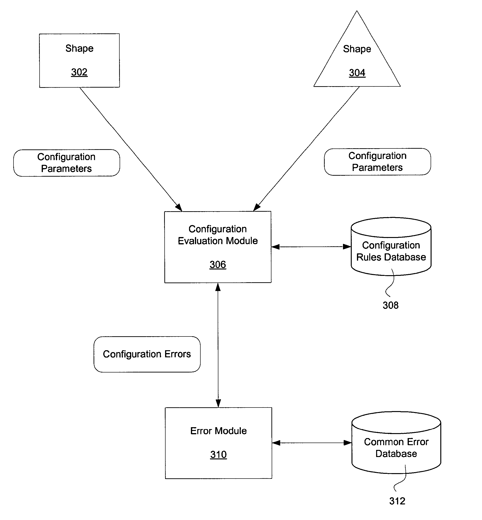
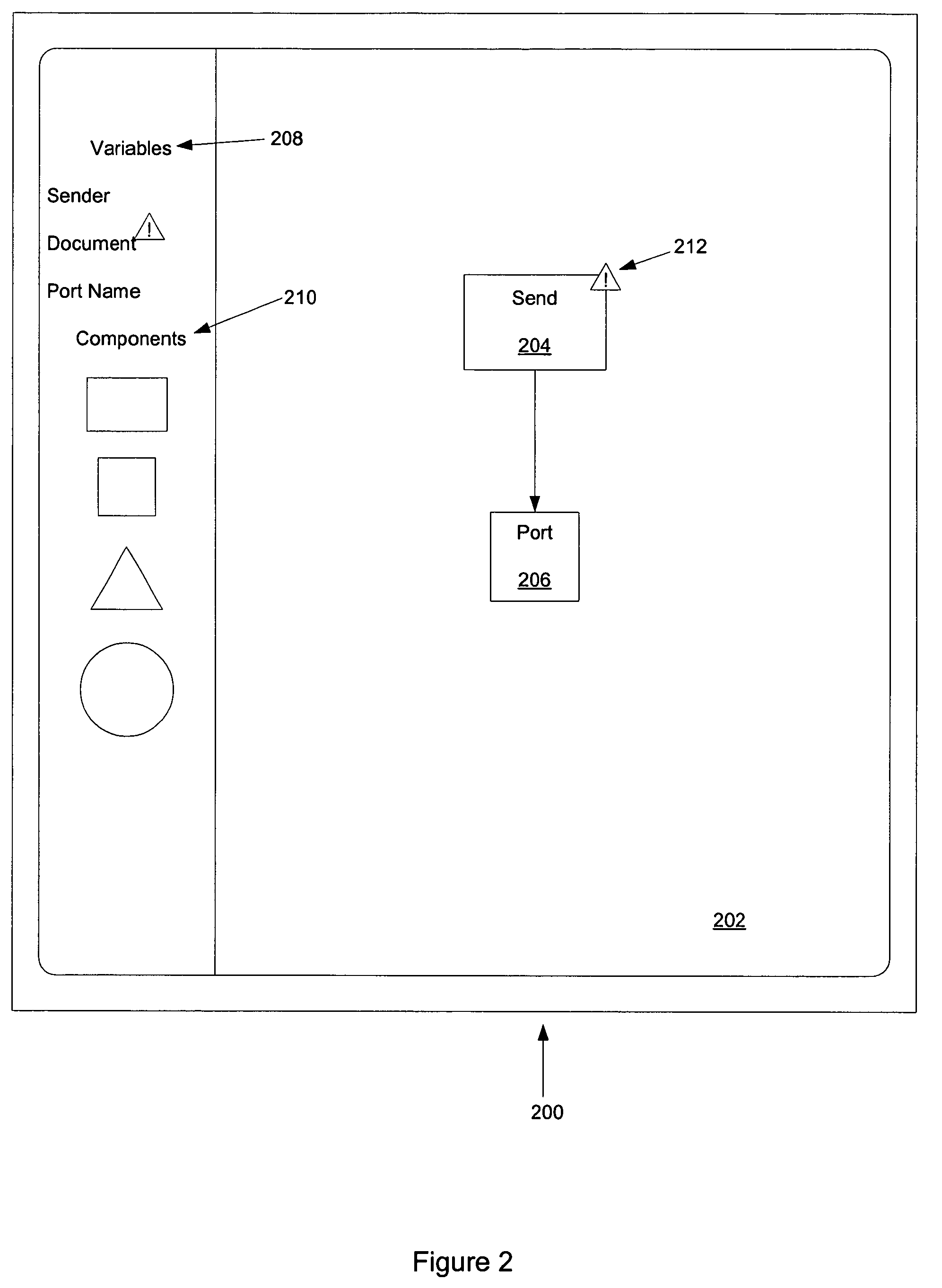
The present invention provides a visual design surface that can identify configuration errors in a way that is not distracting or interruptive to the design workflow. The surface uses inconspicuous icons to help users quickly pinpoint errors and proposes solutions. The configuration parameters of the shapes are periodically checked and error icons are removed when the configuration errors are no longer present. This invention helps improve the efficiency and accuracy of design processes.

Problems solved by technology

For example, if a variable has not been initialized a compilation error identifying this error is presented to the user.
There are several disadvantages in waiting to identify errors until the compilation process.
One disadvantage is that with large designs, it can be difficult for a user to remember the intended function or configuration of an artifact at a later time.
Systems that perform background compilation have been used to present errors to a user during the design process.
Such systems typically list identified errors.
The list of errors can be distracting to the user.
Therefore, there is a need in the art for systems and methods that present configuration errors to a user using a visual design surface such that the presentation method is inconspicuous and minimizes distractions to the user.

Method used


Image

  • Dynamic contextual helper user interface
  • Dynamic contextual helper user interface
  • Dynamic contextual helper user interface

Examples


Embodiment Construction

Exemplary Operating Environment

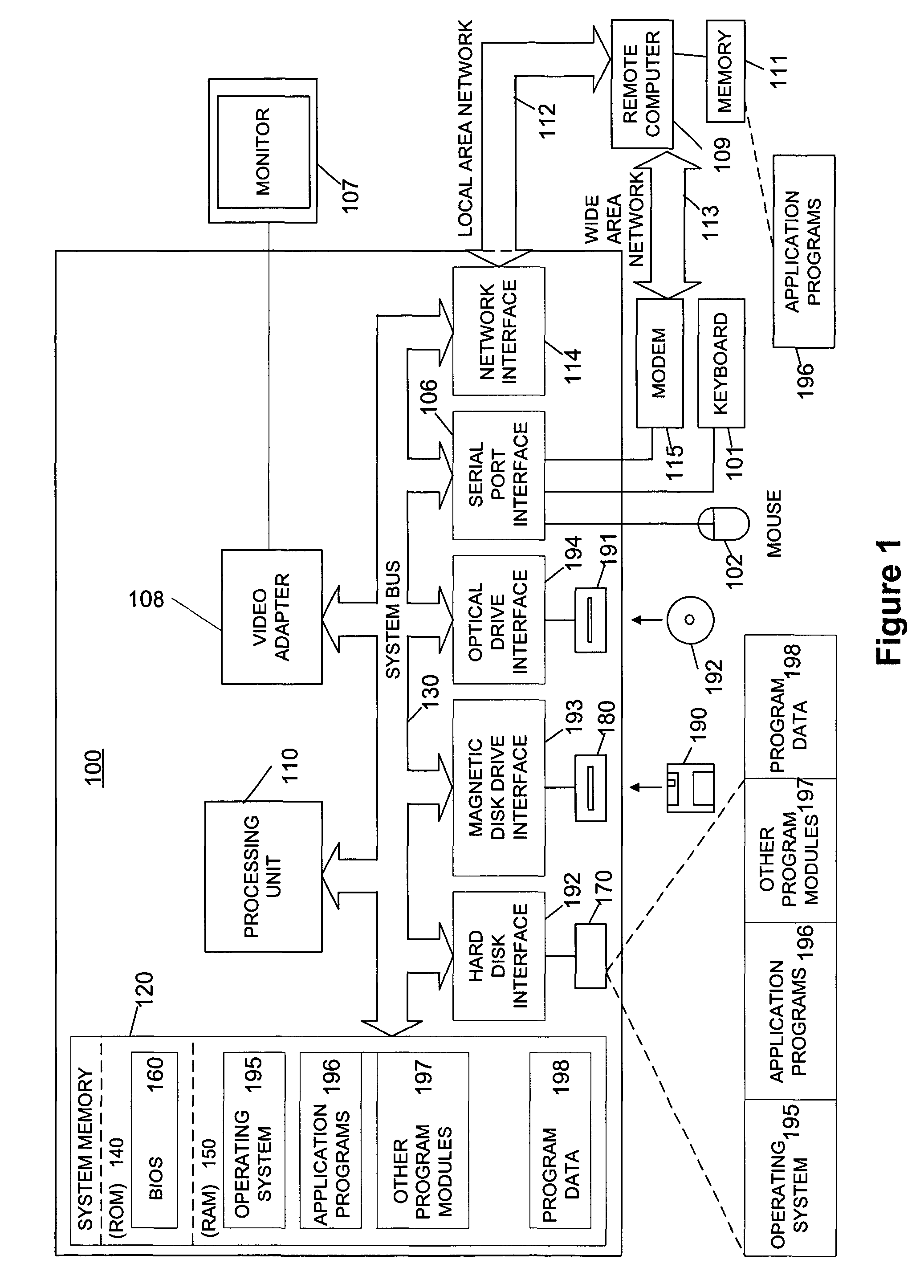
[0017]FIG. 1 is a functional block diagram of an example of a conventional general-purpose digital computing environment that can be used to implement a visual design surface in accordance with various aspects of the present invention. In FIG. 1, a computer 100 includes a processing unit 110, a system memory 120, and a system bus 130 that couples various system components including the system memory to the processing unit 110. The system bus 130 may be any of several types of bus structures including a memory bus or memory controller, a peripheral bus, and a local bus using any of a variety of bus architectures. The system memory 120 includes read only memory (ROM) 140 and random access memory (RAM) 150.

[0018]A basic input / output system 160 (BIOS), containing the basic routines that help to transfer information between elements within the computer 100, such as during start-up, is stored in the ROM 140. The computer 100 also includes a hard disk drive 1...


PUM


Abstract

A visual design surface that identifies configuration errors to a user in an inconspicuous manner is disclosed. Shapes representing software artifacts are arranged on the design surface. Each shape may have one or more configuration parameter. The parameters associated with each shape are analyzed to locate configuration errors. When an error is identified, an error icon is placed next to the shape. The user may select the icon and be presented with one or more proposed solutions.

Description

FIELD OF THE INVENTION[0001]Aspects of the present invention relate to visual design surfaces. More specifically, aspects of the present invention provide a visual design surface that includes icons representing configuration errors and that provide proposed solutions.BACKGROUND[0002]Computer applications that include visual design surfaces are commonly used to generate artifacts such as computer code or to automate processes. On a visual design surface, these artifacts are typically represented by shapes. The shapes placed on the visual design surface are often arranged in a particular order and connected together in a particular fashion to perform specific functions. Each of the shapes also typically includes configuration parameters that are set by the user. After the user lays out the pattern of shapes and sets the appropriate configuration parameters, the design is compiled.[0003]During the compilation process errors are identified and presented to the user. For example, if a v...

Claims


Application Information

Patent Timeline
Patent Type & Authority Patents(United States)
IPC IPC(8): G06F9/44G06F3/00G06F3/048G06F11/00G06F11/32G06F15/173
CPCG06F3/0481G06F9/4446G06F11/327G06F9/453
Inventor CORNELIUS, AARONFONG, DAVIDMERCER, JEREMYSTALLO, GIOVANNI
Owner MICROSOFT TECH LICENSING LLC
Learn More