Anti-vibration tube support with locking assembly

a tube support and anti-vibration technology, applied in the direction of machine supports, indirect heat exchangers, lighting and heating apparatus, etc., can solve the problems of causing flow-induced vibrations of oscillatory nature, damage to the bundle, and tube vibration problems may be exacerbated

Inactive Publication Date: 2009-03-24
EXXON RES & ENG CO
View PDF29 Cites 17 Cited by
  • Summary
  • Abstract
  • Description
  • Claims
  • Application Information

AI Technical Summary

Benefits of technology

[0008]It is an aspect of the present invention to provide a support device for a bundle of elongated members having locking assembly that maintains the support device in proper orientation within the bundle while preventing accidental removal of the support device.
[0009]In accordance with the principles of the present invention, a support device for a bundle of elongated members is provided. The bundle of elongated members includes a plurality of spaced rows of elongated members. The bundle may have a square tube pattern configuration, either 90 or 45 degree layout. The bundle of elongated members having an interior and an outer periphery. The support device includes an elongated support adapted to be located between adjacent spaced rows of elongated members. Each elongated support is preferably formed from a pair of metal strips that are selectively secured together. The elongated support having a first side and a second side. The first side being arranged to be positioned adjacent one row of the spaced rows of elongated members and the second side being arranged to be positioned adjacent another row of the spaced rows of elongated members. The elongated support having a plurality of support members spaced along the elongated support. Each support member has a first supporting assembly located on the first side for supporting one of the elongated members in the one row and a second supporting assembly located on the second side for supporting one of the elongated members in the other row. The plurality of support members are preferably spaced along substantially the entire length of the elongated support. The supporting assemblies engage the elongated members within the bundle to stabilize the elongated members and thus reduce vibration when fluids flow through and around the elongated members at higher velocities.
[0010]In order to maintain proper orientation of the support devices within the bundle of elongated members and prevent removal of the same, the support device further includes at least one locking assembly for locking the support device between the adjacent rows of elongated members. The locking assembly prevents inadvertent removal after the support device has been properly oriented within the bundle of elongated members. Each locking assembly is located between adjacent supporting assemblies. Each locking assembly is sized to contact adjacent elongated members in the same row of elongated members in the bundle, which prevents the displacement of the support device with respect to the bundle of elongated members. Preferably, the locking assembly having a thickness that is greater than the thickness of the supporting assemblies. Each locking assembly may extend from opposing sides of the elongated supports. It is also contemplated that the locking assembly may extend only from a single side of the elongated support such that the locking assembly contacts the adjacent elongated members on only one side of the support.
[0012]In accordance with an embodiment of the present invention, each locking assembly includes a locking block having a slot formed therein. The slot is sized to receive a portion of the elongated support therein. The locking block is preferably formed from metal. The locking block may be formed as a cast component or a strip of metal that is bent to form a generally U-shape. The locking block preferably contains rounded edge surfaces to prevent damage to the elongated members contacted the locking assembly.

Problems solved by technology

Fluid flow patterns around the tubes as well as the changes in the temperature and density of the fluids which arise as a result of the heat exchange between the two fluids flowing in and around the tubes may give rise to flow-induced vibrations of an oscillatory nature in the tube bundle.
If these vibrations reach certain critical amplitudes, damage to the bundle may result.
Tube vibration problems may be exacerbated if heat exchange equipment is retubed with tubes of a different material to the original tubes, for example, if relatively stiff materials are replaced with lighter weight tubes.
Flow-induced vibration may also occur when equipment is put to more severe operating demands, for example, when other existing equipment is upgraded and a previously satisfactory heat exchanger, under new conditions, becomes subject to flow-induced vibrations.
While the cables are effective in securing the support devices within the bundle, the use of such cables has potential drawbacks.
There may be difficulties associated with installing the cable around the tube bundle.
The cable may fret at the point where the cable passes through an associated aperture in the support device, which could lead to the potential failure of the cable.
Additionally, the flow of fluid around the tubes of the tube bundle may cause the cable to rub on the outer surface of the outermost tubes in the tube bundle, which may cause wear.

Method used


Image

  • Anti-vibration tube support with locking assembly
  • Anti-vibration tube support with locking assembly
  • Anti-vibration tube support with locking assembly

Examples


Embodiment Construction

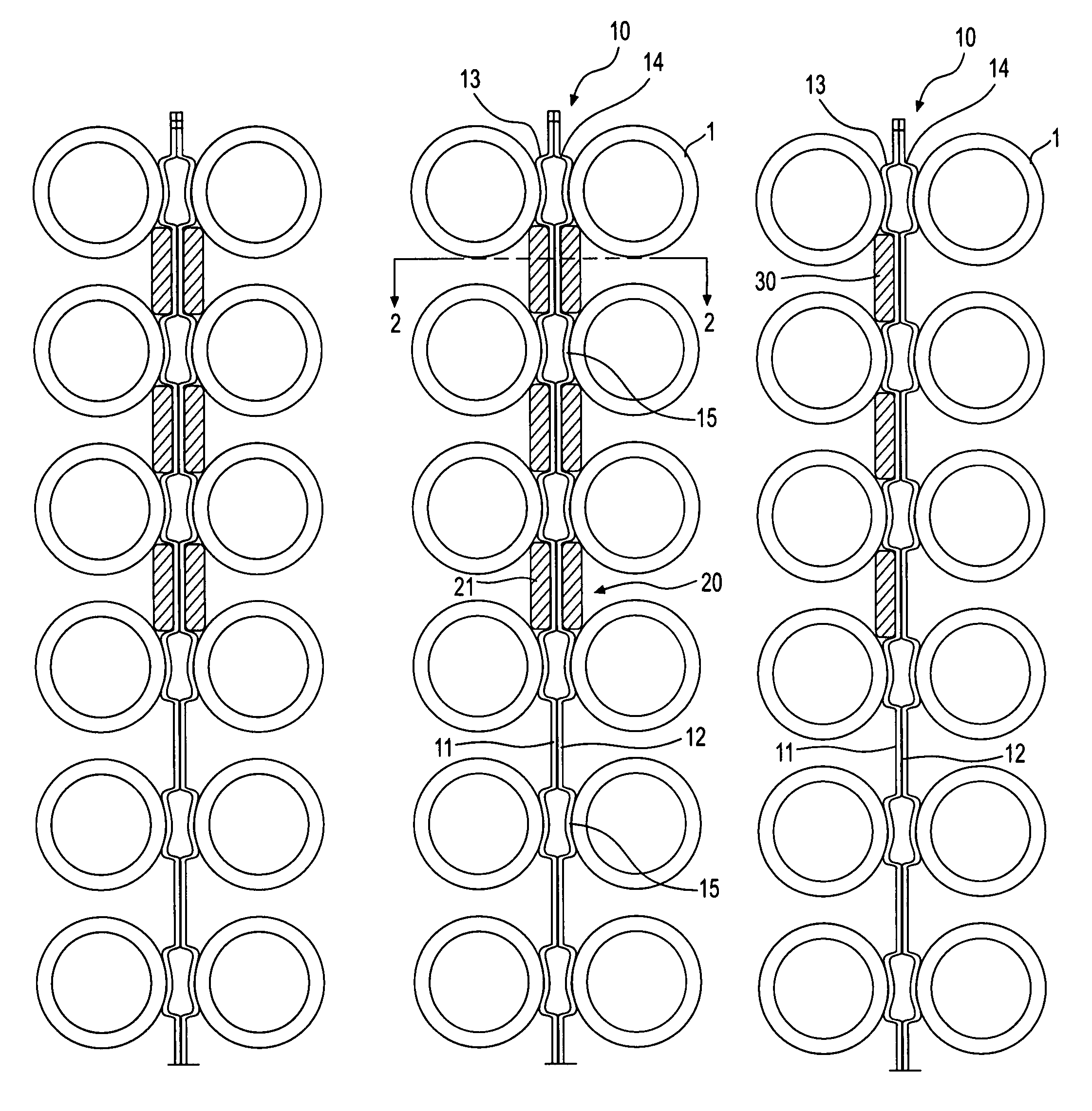
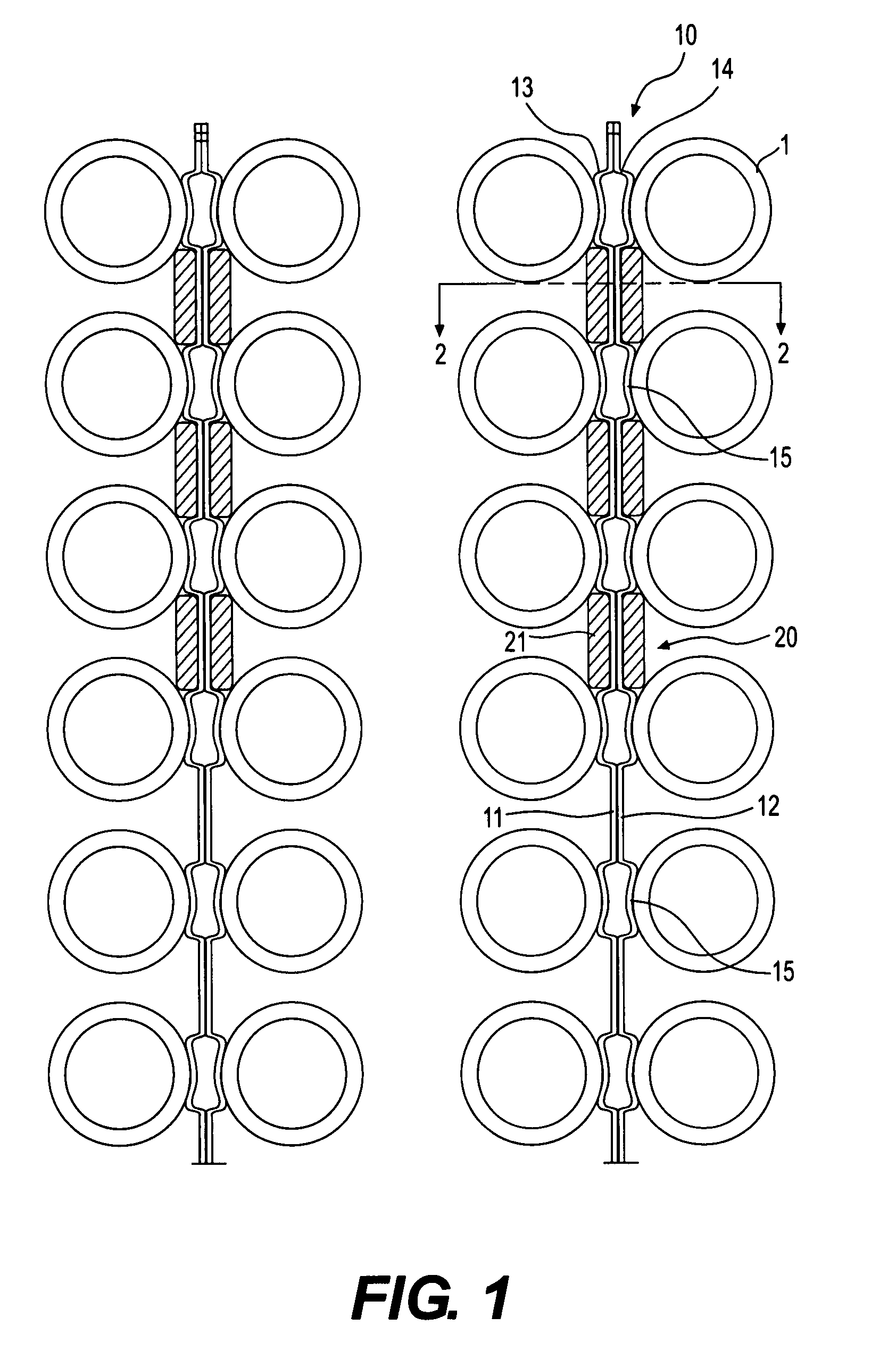
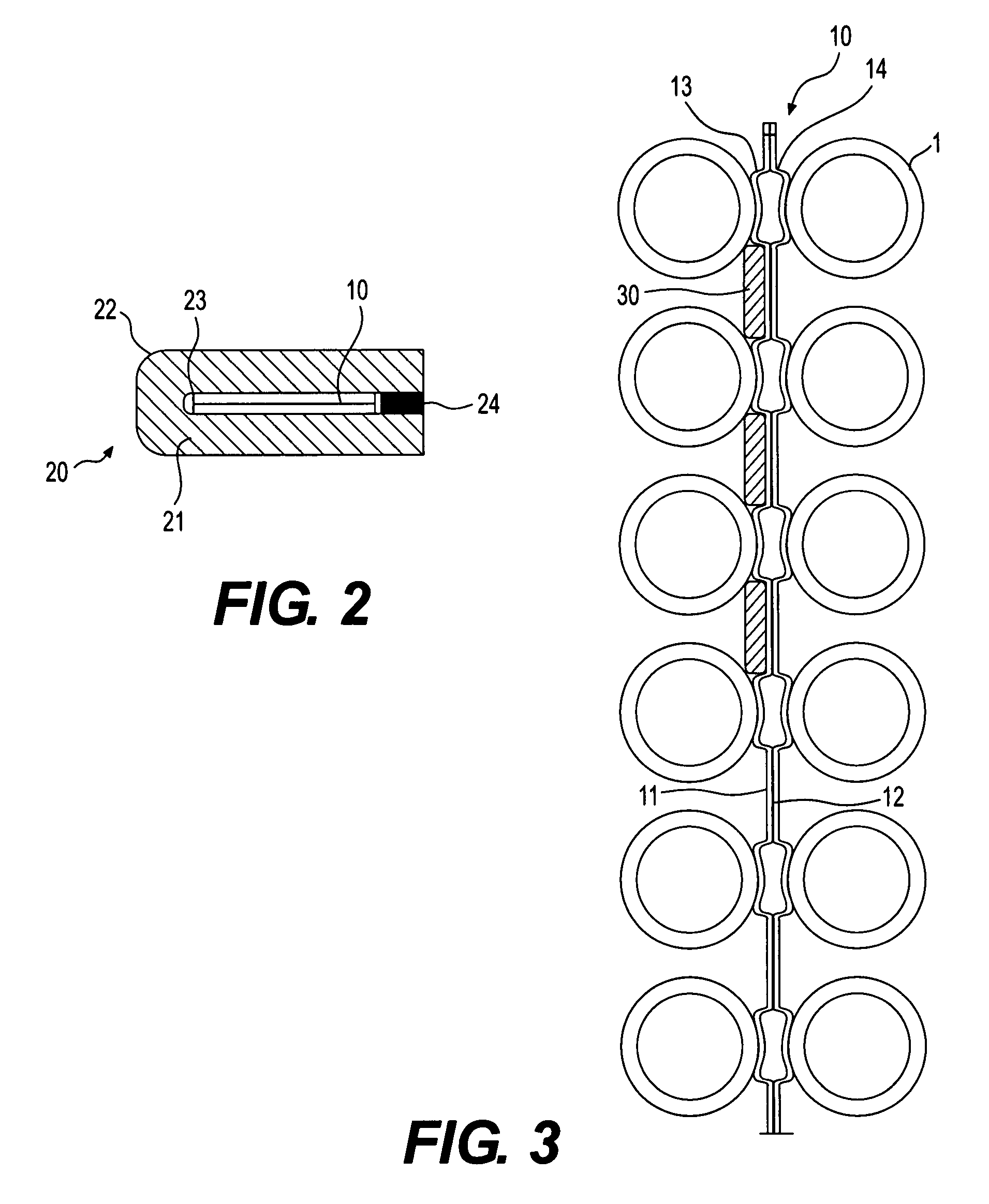
[0017]FIG. 1 illustrates a portion of a bundle of elongated members 1. The elongated members 1 are arranged in rows with a space or lane separating adjacent rows of members 1. The elongated members 1 preferably form part of a fluid handling device. The fluid handling device is preferably a heat transfer device such as, for example, a heat exchanger. The elongated members 1 may be rods or hollow tubes that are capable of transferring heat to a fluid flowing through the device. The rods or hollow tubes may be part of a shell and tube heat exchanger or other suitable heat transfer assembly (whether for heating or cooling). As described above, the elongated members 1 may experience or be subject to vibration as a result of fluid flow in and around the elongated members 1.

[0018]In order to mitigate vibration and improve performance, at least one support device 10 may be inserted in the lane between adjacent rows of elongated members 1, as shown for example in FIG. 1. The support device 1...


PUM


Abstract

A support device for a bundle of elongated members and a locking assembly for securing the same within the bundle are disclosed. The support device includes an elongated support adapted to be located between adjacent spaced rows of elongated members, wherein the elongated support having a first side and a second side, wherein the first side being arranged to be positioned adjacent one row of the spaced rows of elongated members and the second side being arranged to be positioned adjacent another row of the spaced rows of elongated members. The support device includes a plurality of support members spaced along the elongated support, wherein each support member have a first supporting assembly located on the first side for supporting one of the elongated members in the one row and a second supporting assembly located on the second side for supporting one of the elongated members in the other row. At least one locking assembly is provided for locking the support device between the adjacent rows of elongated members, wherein each of the at least one locking assembly being located on at least one of the first side and the second side between adjacent supporting assemblies.

Description

FIELD OF THE INVENTION[0001]This invention relates to support devices for supporting elongated members. In particular, the present invention relates to support devices for use in connection with tube bundles in heat exchangers and similar fluid-handling equipment to reduce vibration of the tubes within the tube bundle. The support devices in accordance with the present invention include at least one locking assembly to prevent unintentional removal of the support devices once installed in the tube bundle.BACKGROUND OF THE INVENTION[0002]Shell and tube heat exchangers and similar items of fluid handling devices utilize tubes organized in bundles to conduct the fluids through the equipment. In such tube bundles, there is typically fluid flow both through the insides of the tubes and across the outsides of the tubes. The configuration of the tubes in the bundle is set by the tubesheets into which the tubes are set. One common configuration for the tubes is a square formation with the t...

Claims


Application Information

Patent Timeline
Patent Type & Authority Patents(United States)
IPC IPC(8): F28D7/00
CPCF28F9/0132
Inventor WANNI, AMAR S.RUDY, THOMAS M.
Owner EXXON RES & ENG CO
Why Eureka
Try Eureka