Off road vehicle with air intake system

an air intake system and off-road vehicle technology, applied in off-road vehicles, vehicle components, propulsion parts, etc., can solve the problem that the air cleaner is likely to draw water

Active Publication Date: 2009-03-24
YAMAHA MOTOR CO LTD +1
View PDF160 Cites 29 Cited by
  • Summary
  • Abstract
  • Description
  • Claims
  • Application Information

AI Technical Summary

Problems solved by technology

Thus, the air cleaner is likely to draw water when the wheels are submerged.

Method used


Image

  • Off road vehicle with air intake system
  • Off road vehicle with air intake system
  • Off road vehicle with air intake system

Examples


Embodiment Construction

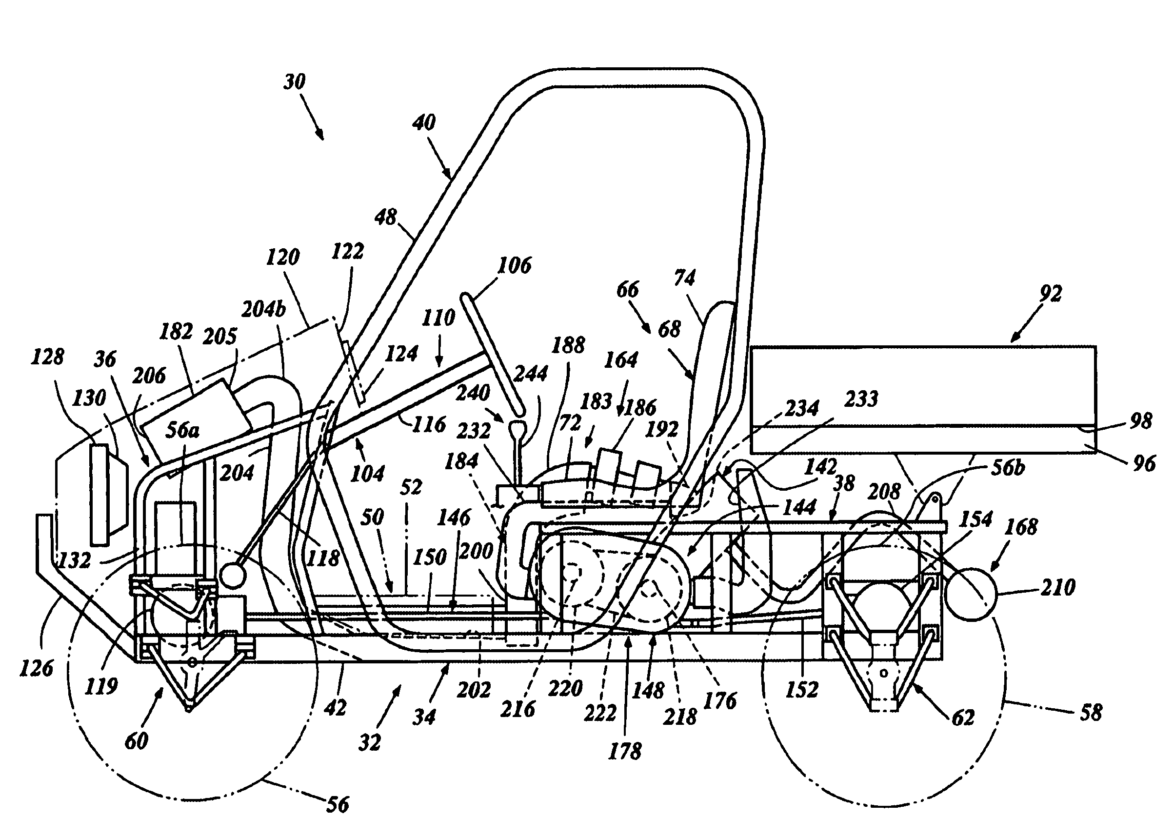
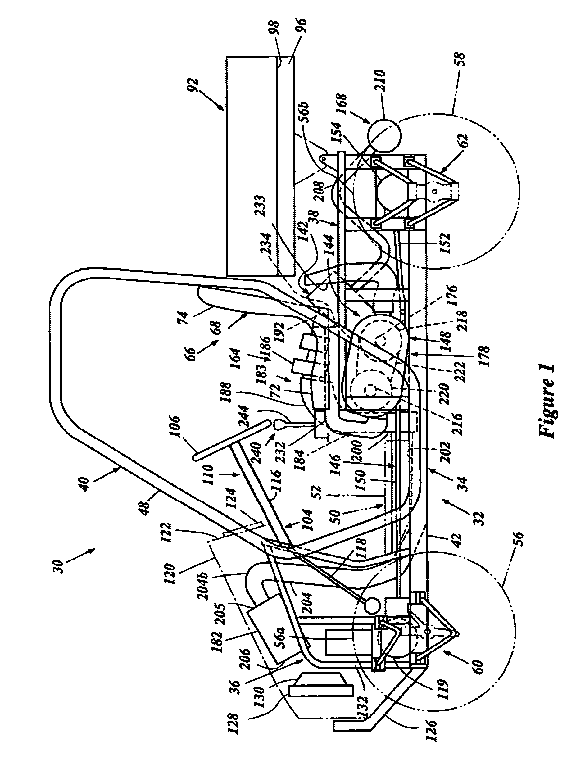
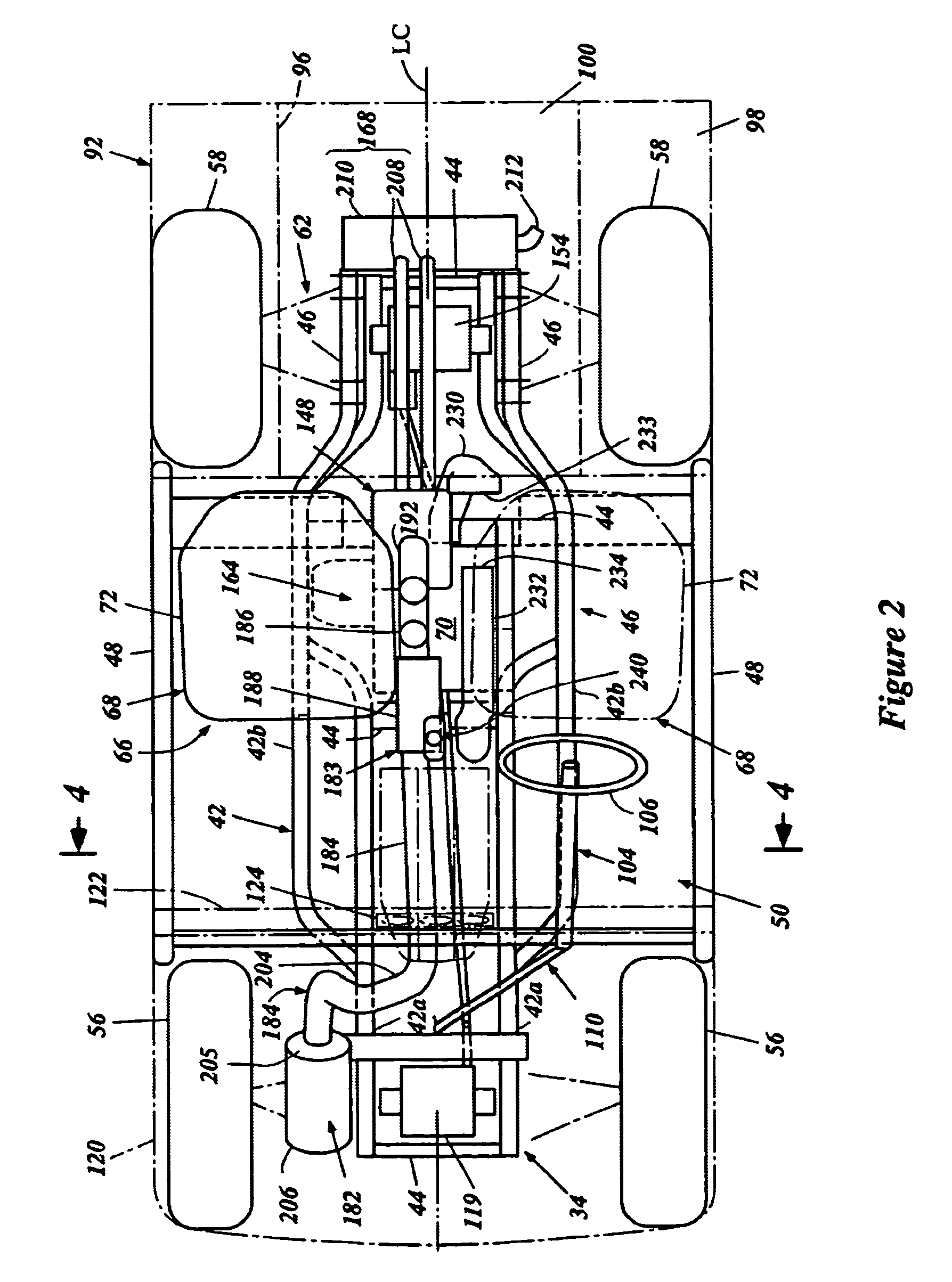
[0025]With reference to FIGS. 1-7, an overall construction of an off-road vehicle 30 is described. While the embodiment is described in connection with this particular type of vehicle, those of skill in the art will appreciate that certain features, aspects and advantages of the present invention may have utility in a wide range of applications for other vehicles, for example, with snowmobiles, tractors, utility vehicles and the like.

[0026]With reference to FIGS. 1, 2 and 4, the off-road vehicle 30 preferably has an open tubular-type frame 32. The illustrated frame 32 comprises a main frame section 34, a front frame section 36, a rear frame section 38 and a compartment frame section (or pillar frame section) 40.

[0027]The main frame section 34 includes a pair of side frame units 42 spaced apart side by side with each other. Each side frame unit 42 comprises a front tubular member 42a (FIG. 2) and a rear tubular member 42b (FIG. 2). Each tubular member 42a, 42b preferably is rectangul...


PUM


Abstract

An off-road vehicle includes a frame and a plurality of wheels. An engine powers the wheels. An air intake system supplies air to the engine. The air intake system has an air inlet through which ambient air enters the intake system. The air inlet is positioned higher than the wheels. An air intake duct extends rearward to the engine from the air inlet. At least a portion of the air intake duct is positioned lower than the tops of the wheels.

Description

PRIORITY INFORMATION[0001]The present application is based on and claims the benefit under 35 U.S.C. § 119(e) of U.S. Provisional Application Nos. 60 / 459,958 and 60 / 460,068, both filed on Apr. 2, 2003, the entire contents of which is hereby incorporated by reference.BACKGROUND OF THE INVENTION[0002]1. Field of the Invention[0003]The present invention generally relates to an air intake system for an off-road vehicle.[0004]2. Description of Related Art[0005]Off-road vehicles are designed to be operated over rugged terrain. These vehicles are often operated on unpaved terrain such as, for example, steep inclines and declines, rough roads, and areas covered in mud and water.[0006]The off-road vehicles typically include a frame that is supported by wheels. In one common arrangement, the vehicle has four wheels, i.e., a pair of front wheels and a pair of rear wheels. An internal combustion engine is employed to power at least the rear or front wheels, and most commonly, all of the wheels....

Claims


Application Information

Patent Timeline
Patent Type & Authority Patents(United States)
IPC IPC(8): B60K13/02
CPCB60K13/02B60K2005/003B60Y2200/20
Inventor KATO, EIJIIZUMI, KAZUHIKOINUI, AKIRATANAKA, NORIHIKONASH, COLBY
Owner YAMAHA MOTOR CO LTD
Why Eureka
Try Eureka