Portable Energy Generation Systems

a technology of energy generation system and portable generator, which is applied in the direction of mechanical energy handling, machines/engines, mechanical equipment, etc., can solve the problems of limited placement options, high operating and maintenance costs of traditional generator sets, and large typical diesel or natural gas mobile generator sets, etc., to increase the time between overhauls and prolong the time

Active Publication Date: 2010-03-25
ARIZONA COMMERCE AUTHORITY
View PDF24 Cites 55 Cited by
  • Summary
  • Abstract
  • Description
  • Claims
  • Application Information

AI Technical Summary

Benefits of technology

[0019]In accordance with another preferred embodiment hereof, this invention provides a method of increasing the time between overhauls within at least one aviation-derived engine during use in non-aviation service, such method comprising the steps of: identifying within such at least one aviation-derived engine, at least one first set of engine components to be modified to extend the time between overhauls of such at least one aviation-derived engine during such non-aviation service; providing at least one second set of industrialized engine components to replace substantially such engine components within such at least one set; and replacing such engine components of such at least one set with such at least one industrialized engine component; wherein such at least one first set comprises at least about fifty percent of the overall engine components comprising such at least one aviation-derived engine; and wherein such replacement of engine components extends the time between overhauls of such at least one aviation-derived engine during such non-industrial service.

Problems solved by technology

Typical diesel or natural gas-powered mobile generator sets are large, heavy, and expensive to transport.
Furthermore, such traditional generation systems often require a high level of site coordination to address issues related to the physical size and structural loading imposed by the location of such units in and around a building structure, often resulting in limited placement options.
The operation and maintenance of such traditional generator sets tends to be high, as any maintenance of the power components requires difficult on-site work or the labor-intensive removal and hauling of a generation unit or unit components to a remote service facility.

Method used


Image

  • Portable Energy Generation Systems
  • Portable Energy Generation Systems
  • Portable Energy Generation Systems

Examples


Embodiment Construction

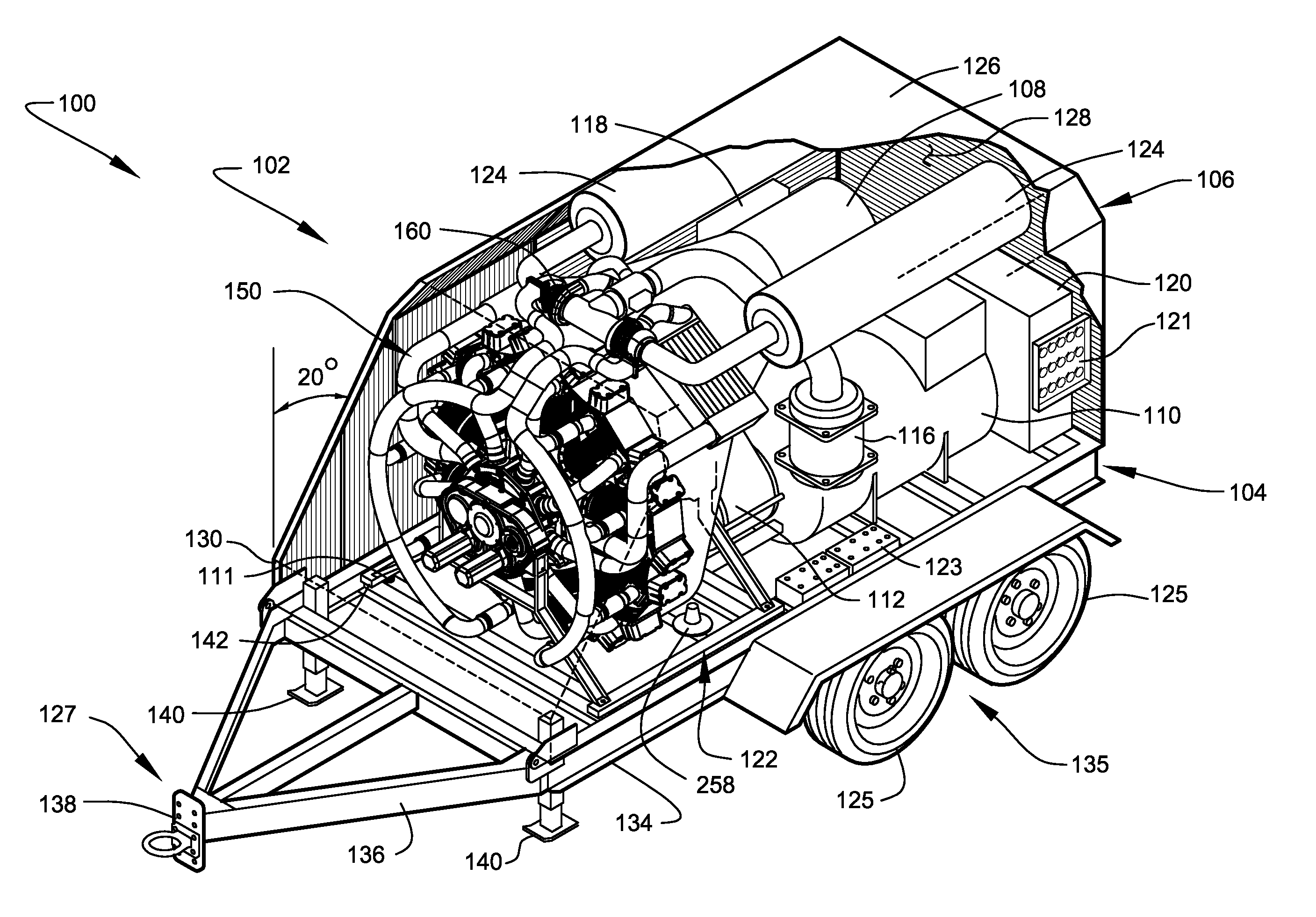
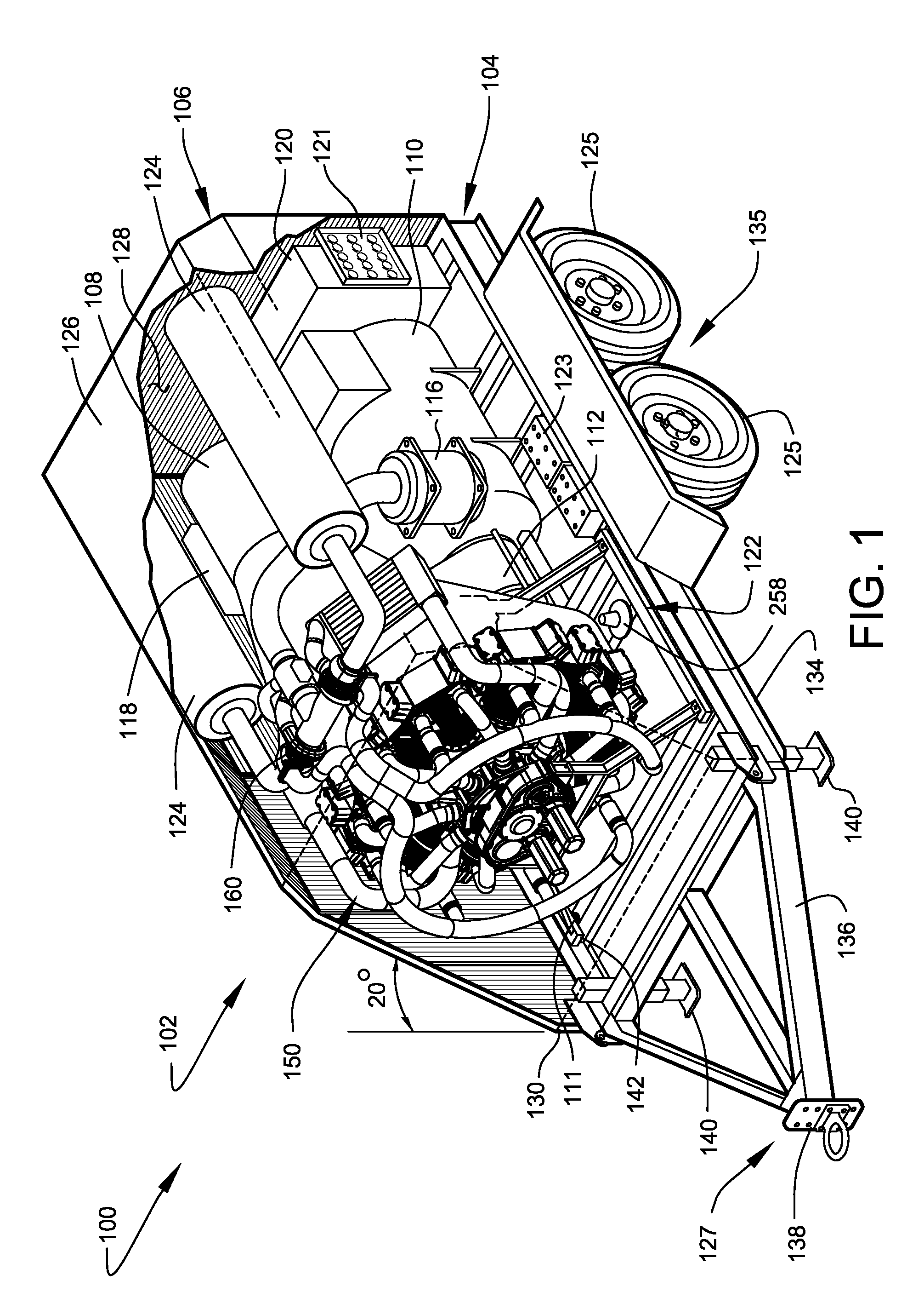
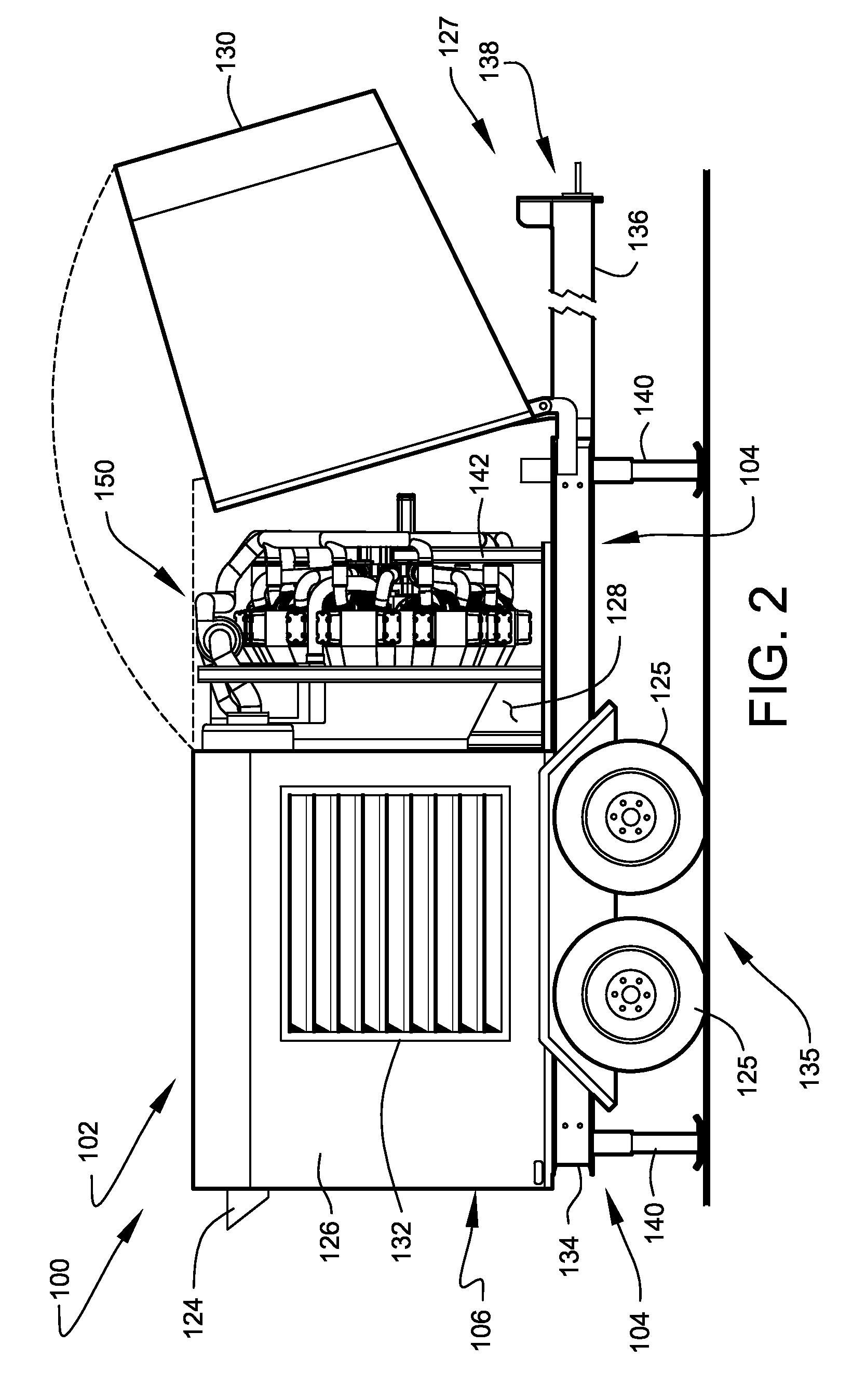
[0063]FIG. 1 shows a perspective view, in partial section, of a highly compact mobile generator set 102 capable of producing electrical power at megawatt output levels, according to a preferred embodiment of the present invention. For clarity of description, a portion of outer enclosure 106 of mobile generator set 102 has been omitted from the illustration of FIG. 1 to better depict the preferred internal arrangements of the apparatus. FIG. 2 shows a side view of the same mobile generator set 102 with a forward portion of outer enclosure 106 arranged to an open configuration.

[0064]The preferred embodiments of portable energy generation system 100, including generator set 102 described herein, preferably comprise high-output electrical generators exhibiting the preferred physical characteristics of compact size, low weight, the ability to use a wide range of conventional fuels, and superior operational reliability. During developmental testing, using industry-standard test conditions...


PUM


Abstract

Portable energy generation systems are disclosed. More particularly, a high-output mobile electrical generator system comprising a radial engine power source providing a highly compact physical format.

Description

CROSS-REFERENCE TO RELATED APPLICATION[0001]The present application is related to and claims priority from prior provisional application Ser. No. 61 / 081,648, filed Jul. 17, 2008, entitled “PORTABLE ENERGY GENERATION SYSTEMS”, and is related to and claims priority from prior provisional application Ser. No. 61 / 122,663, filed Dec. 15, 2008, entitled “PORTABLE ENERGY GENERATION SYSTEMS”, the content of both of which are incorporated herein by this reference and are not admitted to be prior art with respect to the present invention by the mention in this cross-reference section.BACKGROUND[0002]This invention relates to providing a system for improved portable energy generation systems. More particularly, this invention relates to electrical generation systems comprising high-output electrical generators of very compact physical size and low physical weight.[0003]Mobile generator sets are often used to provide emergency, standby, peak shaving, and continuous electrical power to a wide ra...

Claims


Application Information

Patent Timeline
Patent Type & Authority Applications(United States)
IPC IPC(8): F02B63/04F02B33/00F01P3/00
CPCF01B9/023F01N13/04F02B37/001F02B37/007F02B63/04F02B63/047F02B75/222F02B2075/1836F02F1/065Y02T10/144F02B63/044Y02T10/12
Inventor KEALY, JOSEPH P.CARMEN, ANTHONY J.HEISE, DOUGLAS R.KEALY, JANET R.
Owner ARIZONA COMMERCE AUTHORITY
Why Eureka
Try Eureka