Application device for a disk brake

a technology of application device and disk brake, which is applied in the direction of mechanically actuated brakes, actuators, braking elements, etc., can solve the problems of limited application force of the linear application device described above, inability to transmit linear force, and large space requirements for the housing of the brake, so as to achieve the effect of reducing production costs, reducing space requirements, and reducing the number of applications

a technology of application device and disk brake, which is applied in the direction of mechanically actuated brakes, actuators, braking elements, etc., can solve the problems of limited application force of the linear application device described above, inability to transmit linear force, and large space requirements for the housing of the brake, so as to achieve the effect of reducing production costs, reducing space requirements, and reducing the number of applications

US7506732B2Active Publication Date: 2009-03-24WABCO EURO BVBA SPRL

Image

  • Application device for a disk brake
  • Application device for a disk brake
  • Application device for a disk brake

Examples


Embodiment Construction

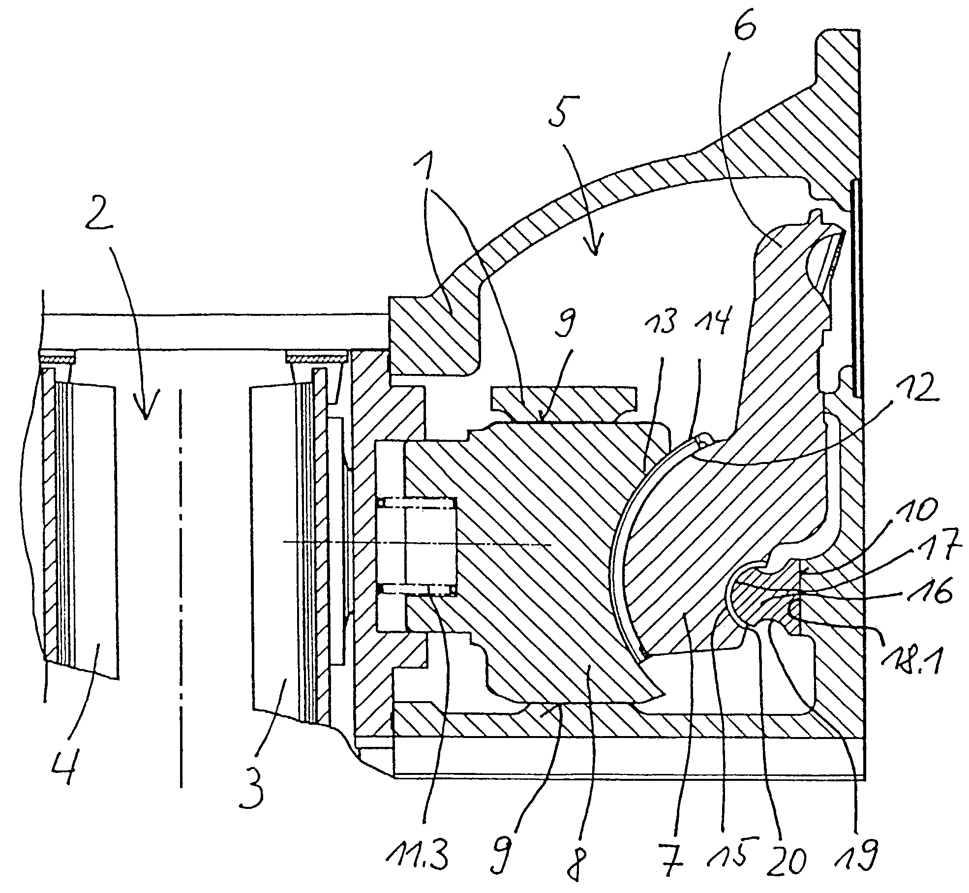
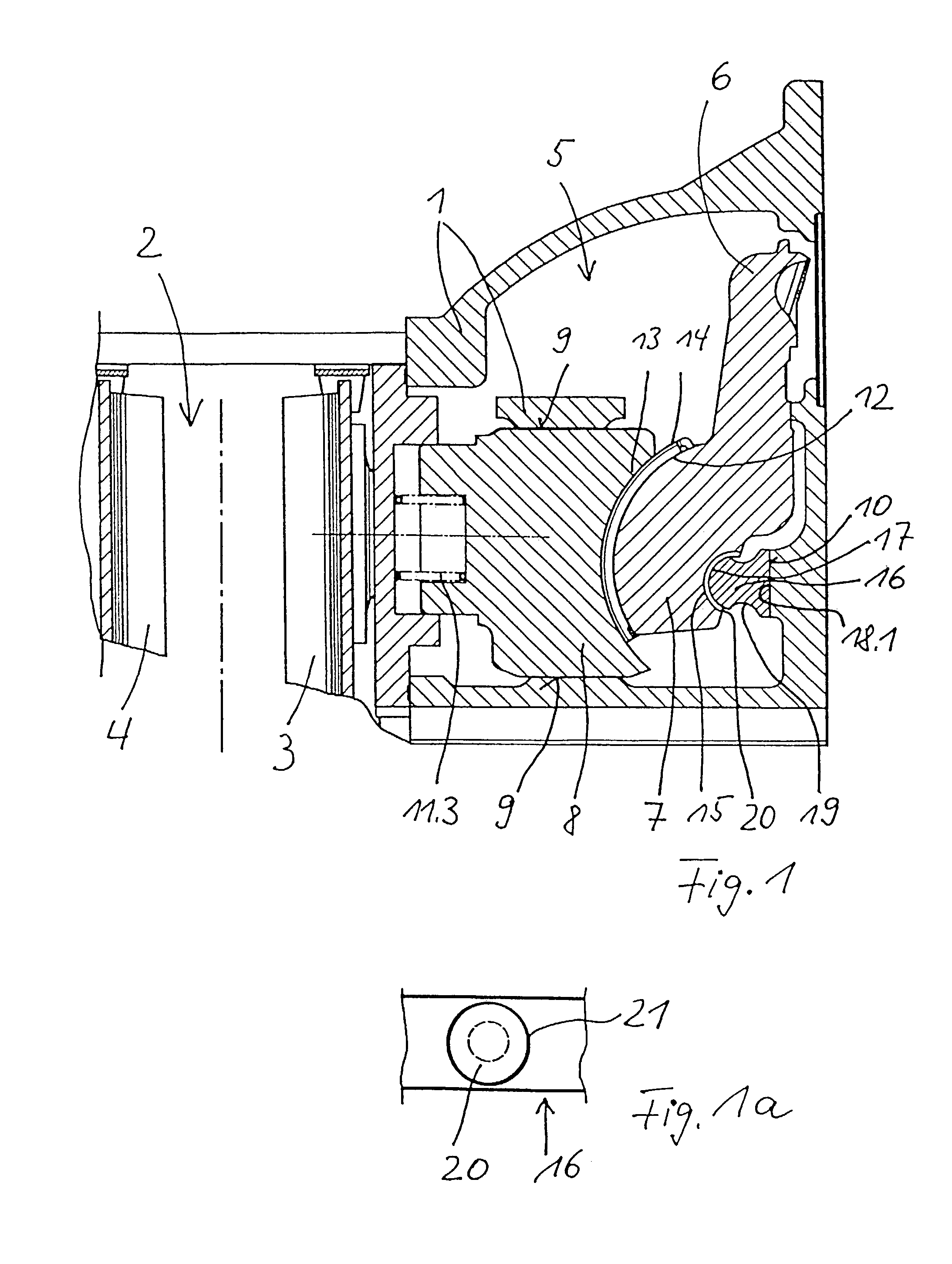
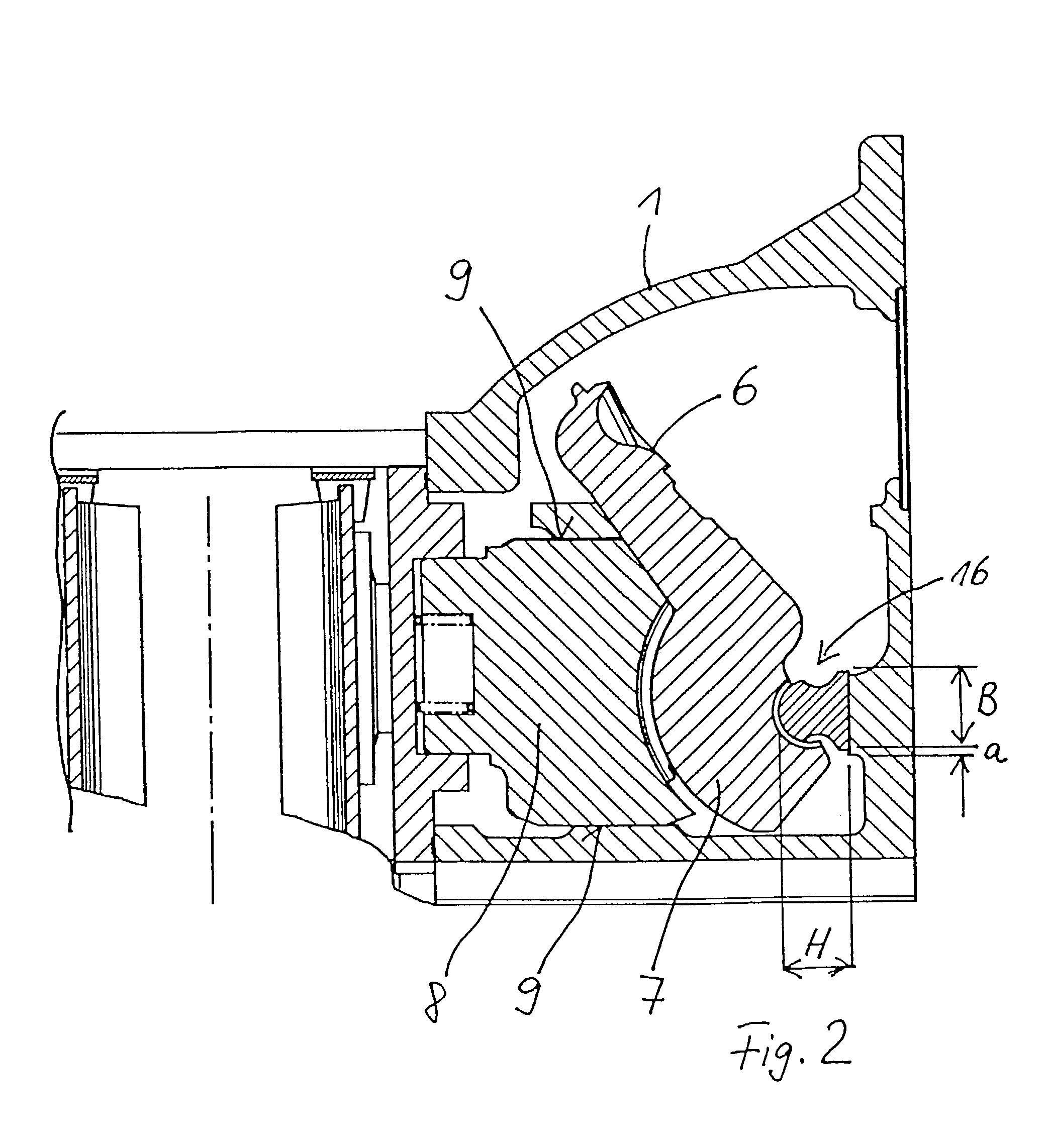
[0039]Each of the Figures shows a disk brake with a caliper 1, the two sidepieces of which extend around a brake disk 2 in the conventional manner. Brake linings 3, 4 are provided on both sides. The application device is designated overall by the reference number 5 and is shown here on the right of the brake disk 2. The caliper 1 can be a sliding caliper or a floating caliper.

[0040]The application device 5 has a brake lever 6, which is connected to an application or brake shaft 7, this shaft being parallel to the main plane of the brake disk 2 in the caliper 1. In addition, a thrust piece 8 is provided (see FIG. 1, for example), which is also transverse to the plane of the brake disk and which is guided in the caliper. The brake lever 6 represents the connection between an actuating device (not shown), which introduces the force, and the application shaft 7. So that the thrust piece 8 can be shifted in a linear manner (in the axial direction) without oscillations, it is supported in...


PUM


Abstract

An application device for a disk brake includes an application shaft extending transversely of an application axis, a first support for supporting the application shaft on an application element, which is shiftable in the direction of the application axis, and a second support for supporting the application shaft on an abutment. The first and second supports have arc-shaped support surfaces on the application shaft, wherein the directions of the curvature of the support surfaces are the same, but the imaginary centers thereof do not coincide. The first and / or the second support has a support element which can shift transversely of the application axis. The support element is a sliding element, which is supported with a second flat slide face on a first flat slide face provided on the abutment or on the application element.

Description

BACKGROUND OF THE INVENTION[0001]1. Field of the Invention[0002]The present invention relates to an application device for a disk brake with:[0003]an application shaft transverse to the application axis;[0004]a first support for supporting the application shaft on an application element, which can move in the direction of the application axis; and[0005]a second support for supporting the application shaft on an abutment,[0006]wherein the first and the second supports have arc-shaped support surfaces on the application shaft, these surfaces curving in the same direction but having imaginary centers which do not coincide; and[0007]wherein the first and / or the second support has a support element which can shift transversely to the application axis.[0008]2. Description of the Related Art[0009]Brake application devices of the type described above are known from, for example, DE 44 30 258 C1. This application device is a so-called linear applicator, which is designed so that the applicat...

Claims


Application Information

Patent Timeline
24 Mar 2009
Publication
US7506732B2
IPC
F16D55/08; F16D65/14; F16D65/18
CPC
F16D65/183; F16D2125/26; F16D2125/32
Inventors
ANTONY, PAUL