Temporary gate support device

a technology of supporting device and gate body, which is applied in the direction of turnstiles, fencing, adhesives, etc., can solve the problems of insufficient meeting and use of gate structures, and achieve the effects of facilitating the rotation of the gate body, facilitating the rotation of the sleeve, and low friction

Inactive Publication Date: 2009-03-24
TURNSTYLE INTPROP
View PDF42 Cites 18 Cited by
  • Summary
  • Abstract
  • Description
  • Claims
  • Application Information

AI Technical Summary

Benefits of technology

[0006]The example gate assembly provides for control of movement through a temporary fence. The gate assembly includes a fixed support that is mounted within the ground by way of a mounting flange. The mounting flange prevents twisting of the support rod during gate operation. Bottom cross-members are attached to a bottom support bearing that is rotatable about the support. The rotational mechanism rotates relative to the support and supports upper cross members. Pushing the upper cross-members causes rotation of the gate assembly to allow movement through the fence.
[0007]The example rotation mechanism operates by supporting the weight of the gate assembly on a ball bearing supported atop the post. A rotatable sleeve includes a bearing surface defining an inner surface that maintains a desired alignment between the fixed plate and the rotatable member. The bearing surface is a low friction material that facilitates rotation of the sleeve relative to the post. The ball bearing provides support for the rotatable portion of the gate assembly while also facilitating rotation of the gate assembly.

Problems solved by technology

The poles are usually simply supported in the ground and are not intended to support anything more than the flexible temporary fencing material.
Disadvantageously, the temporary nature of such fencing prevents the use of a gate structure.
However, in many instances such actions are not desirable and do not adequately meet the desired purpose of restricting access provided by the temporary fence.

Method used


Image

  • Temporary gate support device
  • Temporary gate support device
  • Temporary gate support device

Examples


Embodiment Construction

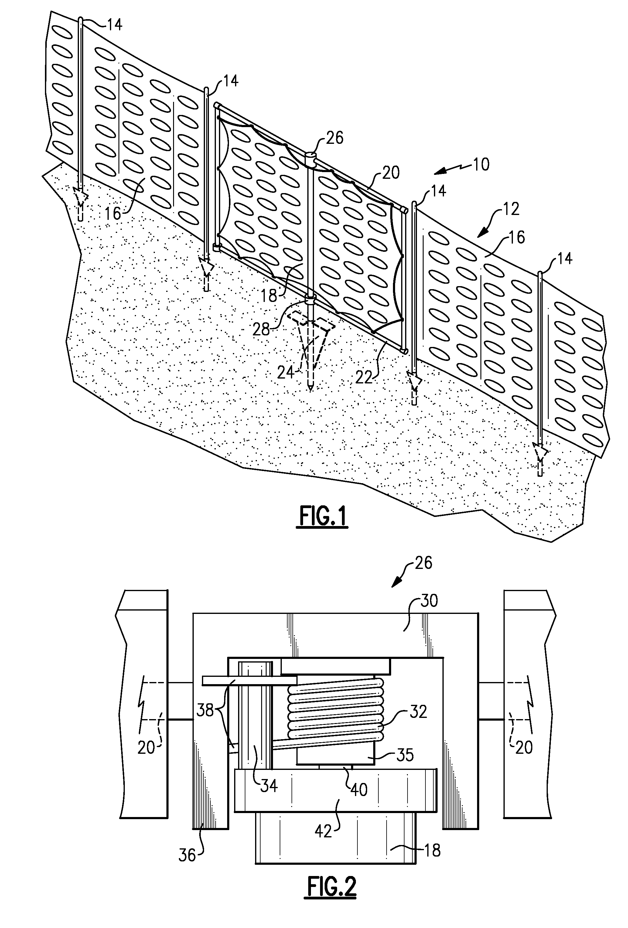
[0016]Referring to FIG. 1, a gate assembly10 provides for control of movement through a temporary fence 12. The temporary fence 12 includes poles 14 received within the ground to support flexible fencing material 16. The flexible fencing material 16 can include plastic mesh fencing, metal mesh or any other material utilized for a temporary fence.

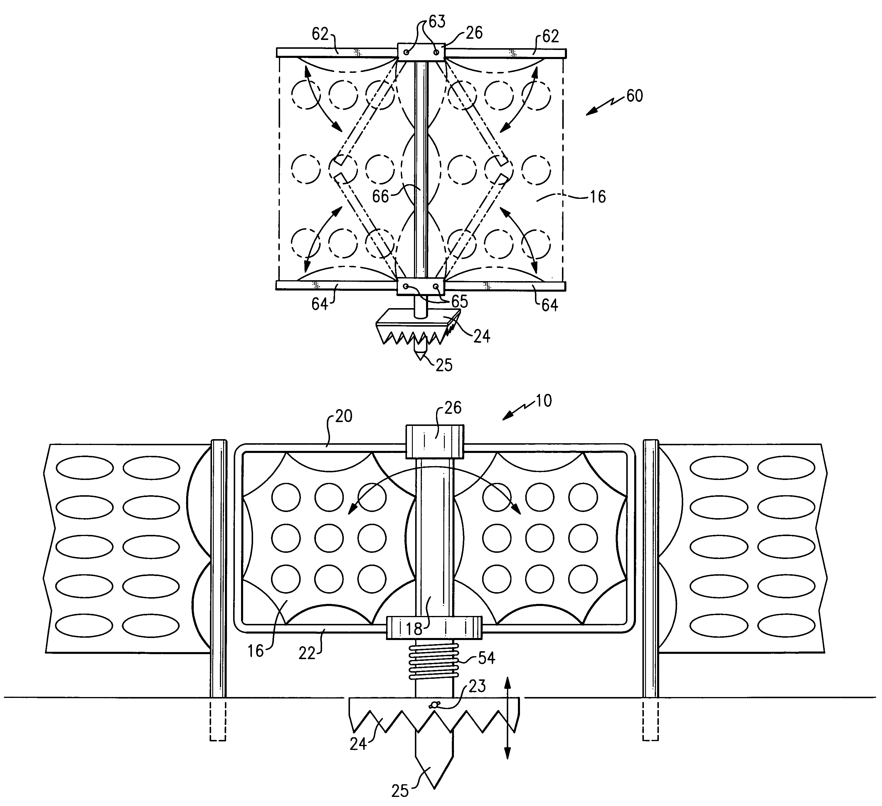
[0017]The gate assembly 10, includes a top cross member 20 and a bottom cross member 22 attached to each other at each end of the gate assembly 10 by a connection rod 23. The top cross-member 20, bottom cross-member 22 and the connection rod 23 support the flexible fencing 16. The gate assembly 10 includes a fixed support 18 that is mounted within the ground by way of a mounting flange 24. The mounting flange 24 prevents twisting of the support rod 18 during gate operation. The mounting flange 25 is staked into the ground along with a portion of the support rod 18 to temporarily secure the gate assembly within a desired opening.

[0018]The bot...


PUM

PropertyMeasurementUnit
flexibleaaaaaaaaaa
areasaaaaaaaaaa
weightaaaaaaaaaa

Abstract

An example temporary gate assembly includes a support mounted within the ground and a rotation mechanism that supports rotation of cross-members about the support. The gate assembly includes a fixed support that is mounted within the ground by way of a mounting flange. The mounting flange prevents twisting of the support rod during gate operation. Bottom cross-members are attached to a bottom support bearing that is rotatable about the support.

Description

CROSS REFERENCE TO RELATED APPLICATION[0001]The application claims priority to U.S. Provisional Application No. 60 / 790,442 which was filed on Apr. 7, 2006.BACKGROUND OF THE INVENTION[0002]This invention generally relates to a temporary gate assembly. More particularly, this invention relates to a rotatable support mechanism for supporting a temporary gate assembly[0003]Temporary fencing is often utilized to restrict access to areas such as construction sites, or special events. The temporary fencing is typically constructed of a flexible material that is easily set up and stored. The temporary fencing is in many instances a plastic mesh material that is strung between stakes or poles stuck in to the ground. The poles are usually simply supported in the ground and are not intended to support anything more than the flexible temporary fencing material.[0004]Disadvantageously, the temporary nature of such fencing prevents the use of a gate structure. An opening is typically created by s...

Claims


Application Information

Patent Timeline
Patent Type & Authority Patents(United States)
IPC IPC(8): E04H17/16
CPCE06B11/04E06B11/08Y10T156/1983
Inventor STULL, EDWARD J.
Owner TURNSTYLE INTPROP
Why Eureka
Try Eureka