
Illumination device for simulating neon lighting

Active Publication Date: 2009-03-24
LUMINII PURCHASER LLC
View PDF6 Cites 68 Cited by
  • Summary
  • Abstract
  • Description
  • Claims
  • Application Information

AI Technical Summary

Benefits of technology

[0007]The present invention is an illumination device for simulating neon or similar lighting, which incorporates a slotted and reflective circuit board to increase light-collection efficiency.
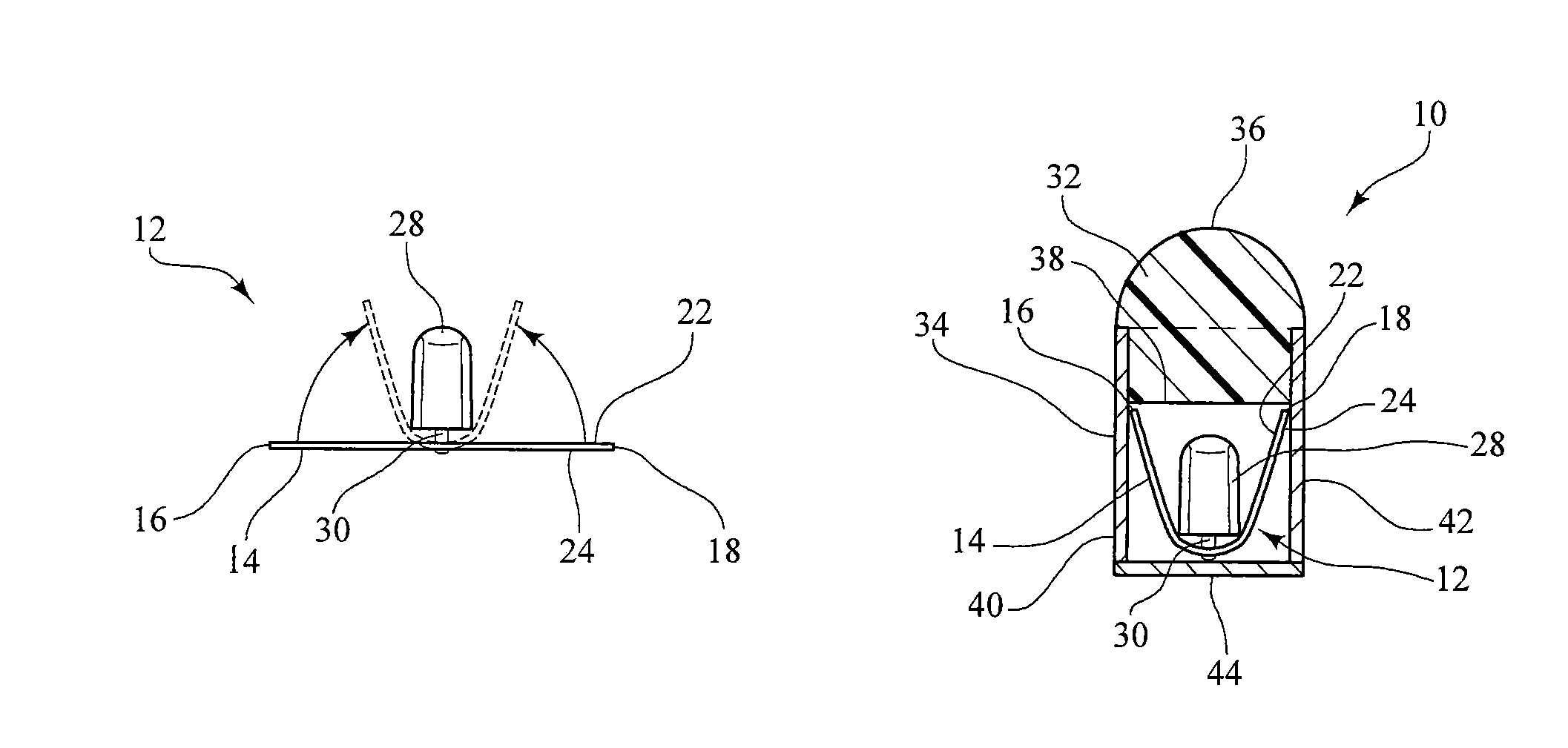
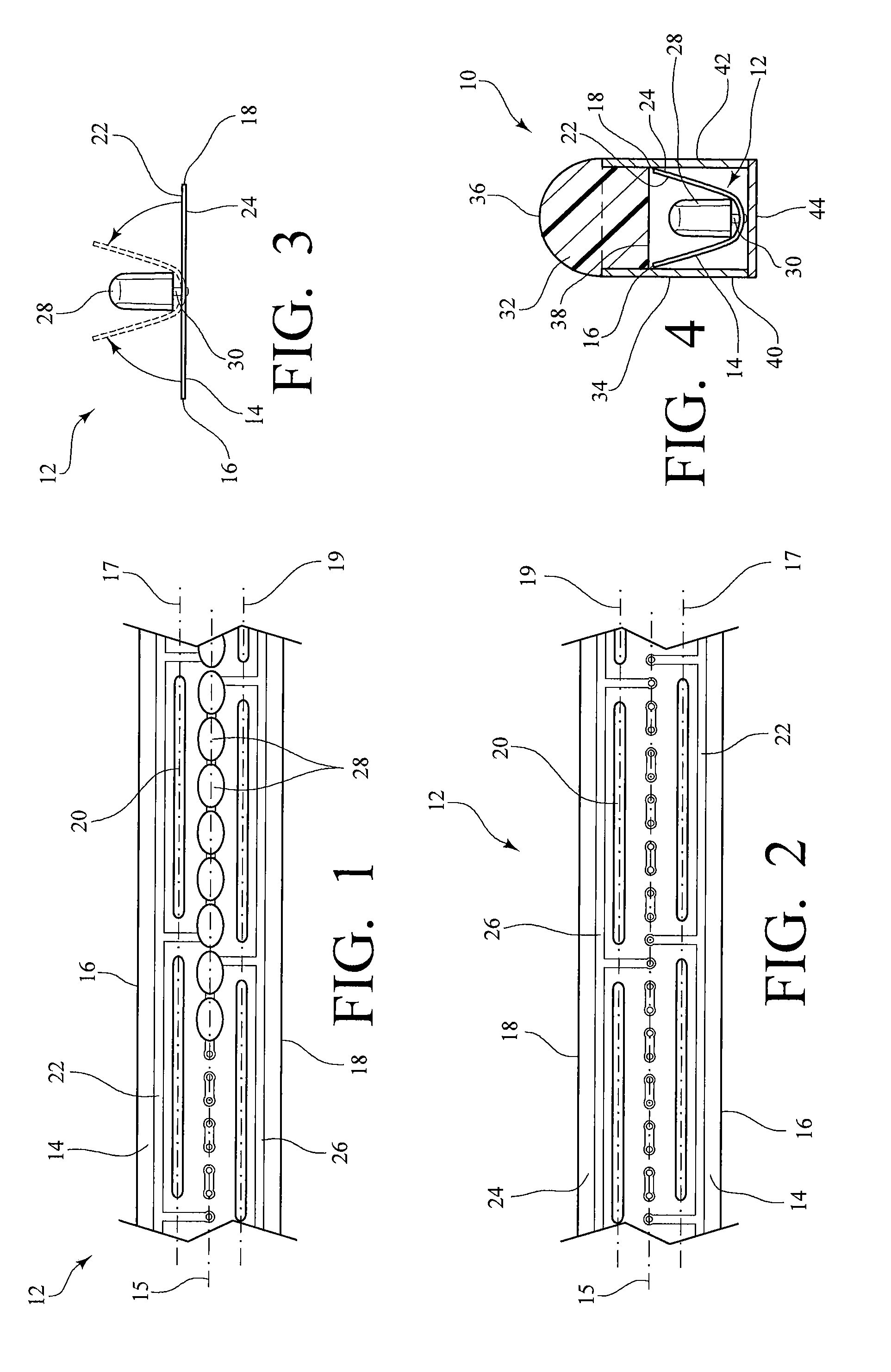
[0009]The slotted circuit board includes a flexible substrate of a predetermined length, having a top surface and a bottom surface. The substrate also has a first lateral (upper) edge, a second lateral (lower) edge, and defines a central longitudinal axis. The circuit board receives and is populated with the plurality of LEDs substantially along the central longitudinal axis, with each individual LED operably connected to a conductive trace applied to a surface of the circuit board. The flexible substrate further defines a plurality of slots oriented longitudinally and along either side of the central longitudinal axis, with the slots defining an upper longitudinal axis and a lower longitudinal axis. The slots facilitate manipulation of the substrate along the respective upper and lower longitudinal axes.

Problems solved by technology

Neon lighting is also recognized as being fragile in nature.
Because of the fragility and heavy weight, primarily due to its supporting infrastructure, neon lighting is expensive to package and ship.
Moreover, it is extremely awkward to initially handle, install, and / or replace.
However, the twin attributes of neon lighting, uniformity and brightness, have proven to be difficult obstacles to overcome as such attempts to simulate neon lighting have largely been stymied by the tradeoffs between light distribution to promote the uniformity and brightness.
While it is important that the disadvantages of neon lighting be avoided (for example, weight and fragility), an illumination device would have little commercial or practical value if the proper light uniformity and intensity could not be obtained.
However, constructing or coating the side walls with light-reflecting material can increase manufacturing costs.

Method used


Image

  • Illumination device for simulating neon lighting
  • Illumination device for simulating neon lighting

Examples


Embodiment Construction

[0015]The present invention is an illumination device for simulating neon or similar lighting, which incorporates a slotted and reflective circuit board to increase light-collection efficiency.

[0016]An illumination device made in accordance with the present invention generally comprises a plurality of light-emitting diodes (LEDs); a housing for receiving the plurality of LEDs; a light-diffusing member positioned adjacent the housing for receiving light emitted from the LEDs; and a slotted and reflective circuit board for operably connecting the LEDs to a power source and / or control system.

[0017]FIGS. 1-2 are partial plan views of the respective top and bottom surfaces of an exemplary slotted circuit board 12 for incorporation into an illumination device 10 made in accordance with the present invention. The slotted circuit board 12 includes a flexible substrate 14 of a predetermined length, having a top surface 22 and a bottom surface 24. The substrate 14 also has a first lateral (up...


PUM


Abstract

An illumination device generally comprises a plurality of light-emitting diodes (LEDs); a housing for receiving the plurality of LEDs; a light-diffusing member positioned adjacent the housing for receiving light emitted from the LEDs; and a slotted and reflective circuit board for operably connecting the LEDs to a power source and / or control system. The flexible substrate can be manipulated from a first, substantially flat position to a second position by folding the substrate along upper and lower longitudinal axes defined by slots oriented longitudinally and along either side of a central longitudinal axis of the substrate, such that the substrate can be inserted into the housing in an approximate U-shape. By manipulating the substrate from the first position to the second position in this manner, light from the LEDs that is not directly emitted into the light-diffusing member is collected and reflected by the circuit board into the light-diffusing member.

Description

BACKGROUND OF THE INVENTION[0001]The present invention relates to an illumination device for simulating neon or similar lighting, and more particularly, to an illumination device incorporating a slotted and reflective circuit board to increase light-collection efficiency.[0002]Neon lighting, which is produced by the electrical stimulation of the electrons in the low-pressure neon gas-filled glass tube, has been a main stay in advertising and for signage. A characteristic of neon lighting is that the tubing encompassing the gas has an even glow over its entire length irrespective of the viewing angle. This characteristic makes neon lighting adaptable for many advertising applications, including script writing and designs, because the glass tubing can be fabricated into curved and twisted configurations simulating script writing and intricate designs. The even glow of neon lighting being typically devoid of hot spots allows for advertising without visual and unsightly distractions. Th...

Claims


Application Information

Patent Timeline
IPC IPC(8): F21V1/06F21V7/18
CPCF21K9/00F21S4/003H05K1/0274H05K1/189H05K2201/10106H05K2201/2054F21Y2101/02F21Y2103/003F21S4/20F21Y2103/10F21Y2115/10F21K9/68
Inventor ERIKSSON, ERIC O.
Owner LUMINII PURCHASER LLC
Learn More