Retractor for performing heart and thorax surgeries

a technology for thoracic surgery and retraction, which is applied in the field of retraction, can solve the problems of trauma in the operating site, surgeons cannot feel exactly how much force is being applied to the patient's body, and the use of positioning devices of this kind has its disadvantages, so as to facilitate one-handed fixing of the swivel position and facilitate the operation of the locking mechanism

Inactive Publication Date: 2009-03-24
KARL STORZ GMBH & CO KG
View PDF10 Cites 1179 Cited by
  • Summary
  • Abstract
  • Description
  • Claims
  • Application Information

AI Technical Summary

Benefits of technology

[0023]Since the swivel position is set by raising the device manually, the surgeon can at any time feel how much force is being applied to the patient's chest, and can thus avoid injury caused by overloading. Once the swivel position required by the surgeon has been reached, it is fixed by means of the locking mechanism.
[0049]This feature has the advantage that the rhombus structure of the surface patterning allows differing resistances to slippage to be created in two different spatial planes perpendicular to one another. Thus, slippage in the direction of the longer diagonal of the rhombus is more likely than in the direction of the shorter diagonal of the rhombus, since the elevations offering resistance are much broader in this direction. There are also far more elevations per unit of length in this direction.

Problems solved by technology

Use of a positioning device of this kind does have its disadvantages, however.
One disadvantage of such a design is that the surgeon cannot feel exactly how much force is being applied to the patient's body, since the change in the swivel position is, as described above, made by turning an adjusting screw.
The application of too much force may lead to trauma in the operating site.
Also, raising one half of the chest by means of an adjusting screw is time-consuming.
This means that the change in the swivel position per turn of the screw is small, thus necessitating prolonged screwing when there is a large change in the swivel position.
This device does however have the disadvantage that it markedly reduces the surgeon's access to the operating site.
Also, the device described in the patent is not symmetrical, and can therefore be used only for one side of the chest, generally the left one.
This means that the retractor cannot be adjusted to accommodate the circumstances of a particular operation.
The device described in this patent is mechanically complicated and consists of a large number of individual parts, which makes it costly to manufacture and complicated to clean and sterilize.
Also, the use of a separate foot can resulting in the foot slipping off and disrupting the operation.
This bulky blade arm / pad arm construction does not enable a surgeon to directly lift the chest but only via a lever.

Method used


Image

  • Retractor for performing heart and thorax surgeries
  • Retractor for performing heart and thorax surgeries
  • Retractor for performing heart and thorax surgeries

Examples


Embodiment Construction

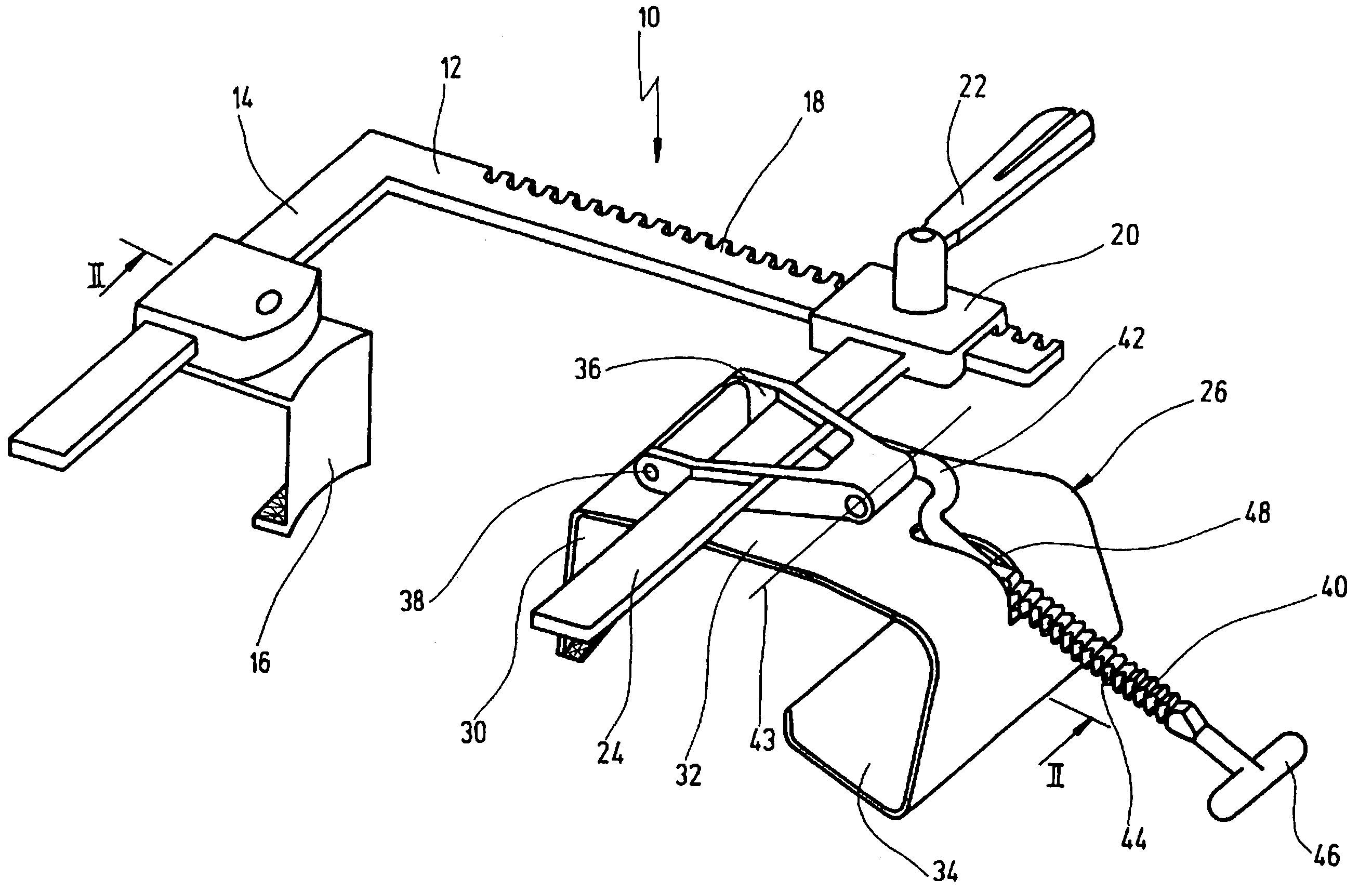
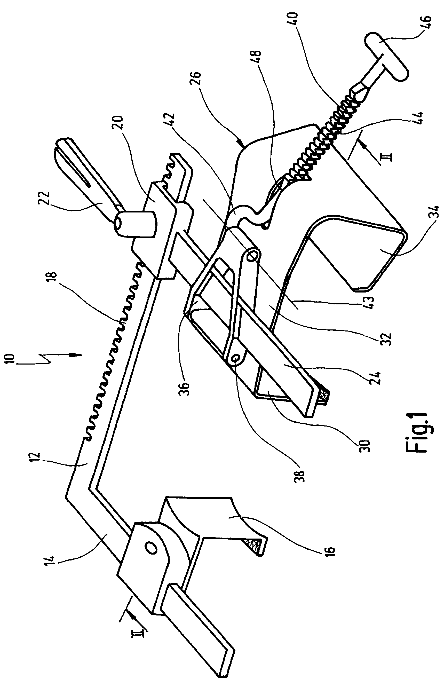
[0061]FIG. 1 shows a retractor in accordance with the invention, in its entirety and marked with the reference numeral 10.

[0062]The retractor 10 has a rail 12 on which a holding arm 14 is mounted at right angles. This holding arm 14 has a valve 16 movably mounted on it.

[0063]The rail 12 also has a rack section 18 on which a drive mechanism 20 is movably mounted. The drive mechanism 20 is moved by means of a cogwheel, not shown in the drawing, which engages with the teeth of the rack section 18. This cogwheel is operated by means of a handle 22.

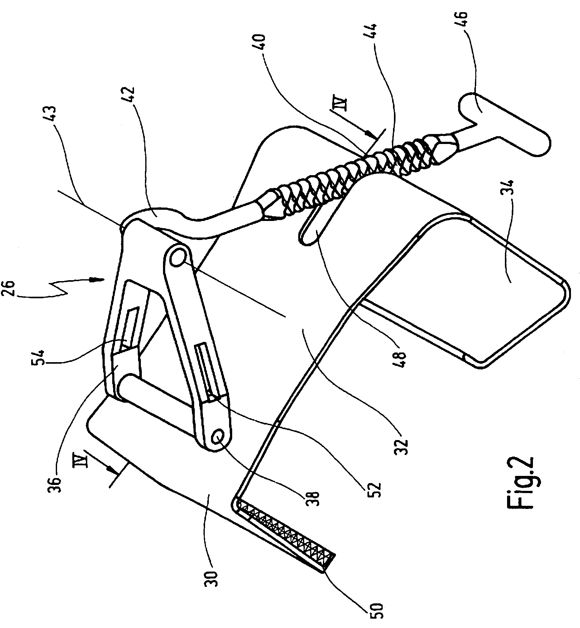
[0064]Also mounted on drive mechanism 20 is a second holding arm 24 which is roughly at right angles to the rail 12. A functional element 26 is movably mounted on this holding arm 24.

[0065]The functional element 26 (see also FIGS. 2 and 3) has a valve section 30 which is roughly parallel to the valve 16, a transverse section 32 which is at right angles to the holding arm 24, and a supporting section 34. The transverse section 32 is pivotably c...


PUM


Abstract

A retractor has a rail, a first holding arm protruding from this rail at an angle at a second holding arm extending approximately parallel to the first holding arm. A distance between the two arms being modifiable. At least one functional element is mounted on one of these holding arms, which functional element has a section extending transversely to the holding arms and a swivel bracket protruding from this transverse section. The functional element being pivotable about a pin extending roughly parallel to the arms via the swivel bracket, a swiveled position can be set by grasping the function element with a hand. A locking mechanism serves for locking the functional element in a swiveled position.

Description

CROSSREFERENCE OF PENDING APPLICATION[0001]This application is a continuation of pending international application PCT / EP2004 / 005468 filed on May 21, 2004 which designates US and which claims priority of German patent application 103 25 393.9 filed on May 28, 2003.BACKGROUND OF THE INVENTION[0002]The invention concerns a retractor with a rail from which a first holding arm protrudes at an angle and with a second holding arm which extends approximately parallel to the first holding arm and the distance from which is modifiable, and with functional elements mounted on the holding arms, of which at least one functional element has a section that extends transversely to a holding arm and which can be pivoted around a pin roughly parallel to one holding arm.[0003]A retractor of this kind is, for example, known from document U.S. Pat. No. 5,025,779 or from U.S. Pat. No. 6,478,734 B1.[0004]Retractors of this kind are for example used as rib retractors in open-heart surgery. The specialist ...

Claims


Application Information

Patent Timeline
Patent Type & Authority Patents(United States)
IPC IPC(8): A61B17/02
CPCA61B17/0206A61B2017/0237
Inventor SCHOELLHORN, JOACHIM
Owner KARL STORZ GMBH & CO KG
Why Eureka
Try Eureka