Single spring supporting device

a support device and single spring technology, applied in the direction of machine supports, building scaffolds, other domestic objects, etc., can solve the problems of increasing the cost of the structure, the spring structure is vulnerable to deformation, etc., and achieve the effect of enhancing the endurance of the spring

Inactive Publication Date: 2009-03-31
HUANG SHIAN NUNG
View PDF7 Cites 81 Cited by
  • Summary
  • Abstract
  • Description
  • Claims
  • Application Information

AI Technical Summary

Benefits of technology

[0008]The invention is to provide a single spring supporting device for supporting a display. An elastic element is arranged along the actuation direction in a fixing mechanism of the supporting device. In cooperation with the operation of a blocking plate and a locking element, the elastic element, not only may proceed a linear telescoping process same as the operational manner of the supporting device, but also may possess the originally supporting force, further enhancing the endurance thereof.

Problems solved by technology

However, since the difference between the arranging direction of the springs and the operating direction of the fixing mechanism relative to the connecting seat and the fixing seat is ignored in this structure's arrangement, the structure of the springs are vulnerable to deformation, influencing the telescoping operation of the springs themselves, which becomes one of the shortcomings.
In addition, the operation of a plurality of springs will increase the structure's cost, which becomes a defect of the structure, otherwise it will be perfect.

Method used


Image

  • Single spring supporting device
  • Single spring supporting device
  • Single spring supporting device

Examples


Embodiment Construction

[0017]In cooperation with attached drawings, the technical contents and detailed description of the present invention are described thereinafter according to a preferable embodiment, being not used to limit its executing scope. Any equivalent variation and modification made according to appended claims is all covered by the claims claimed by the present invention.

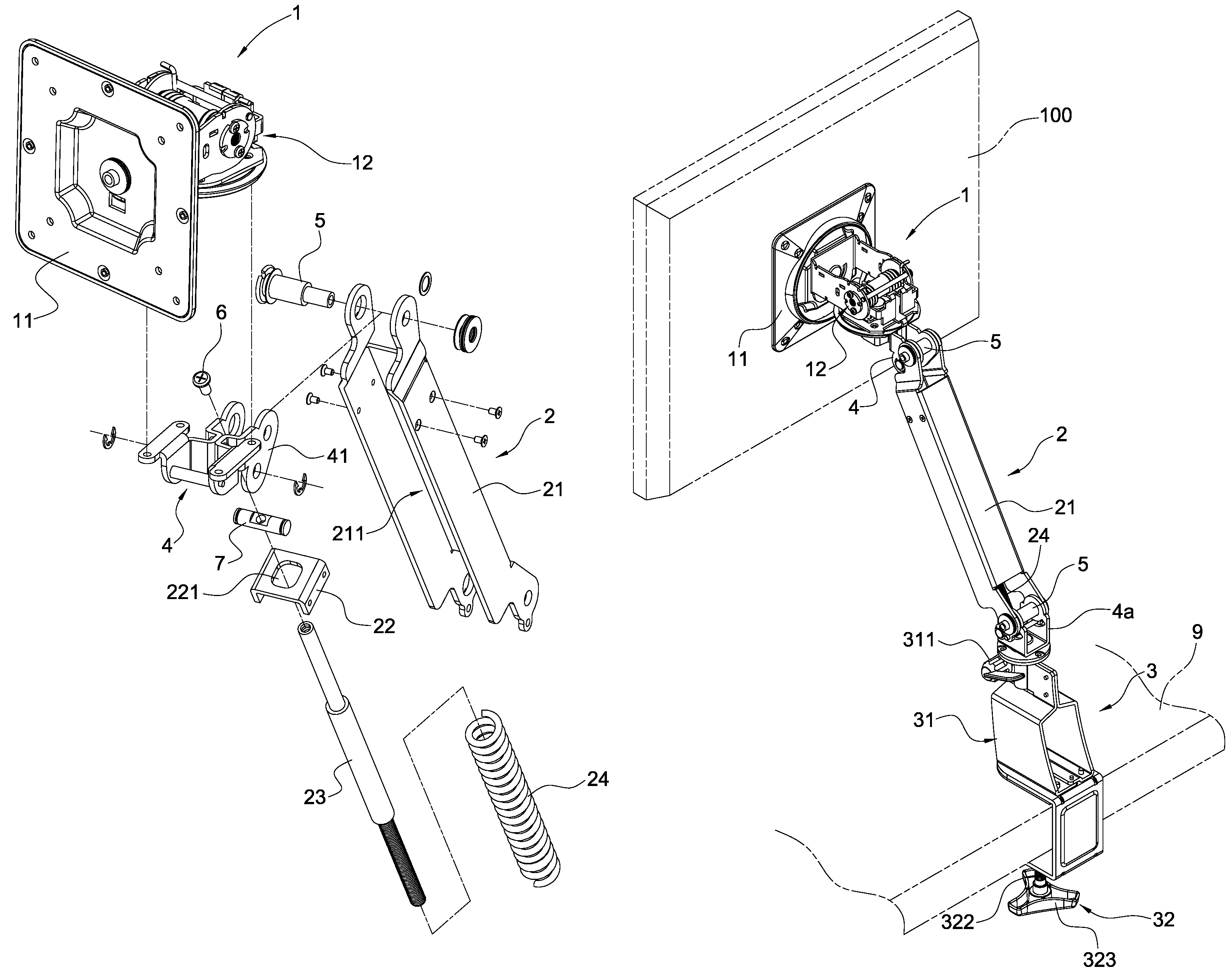
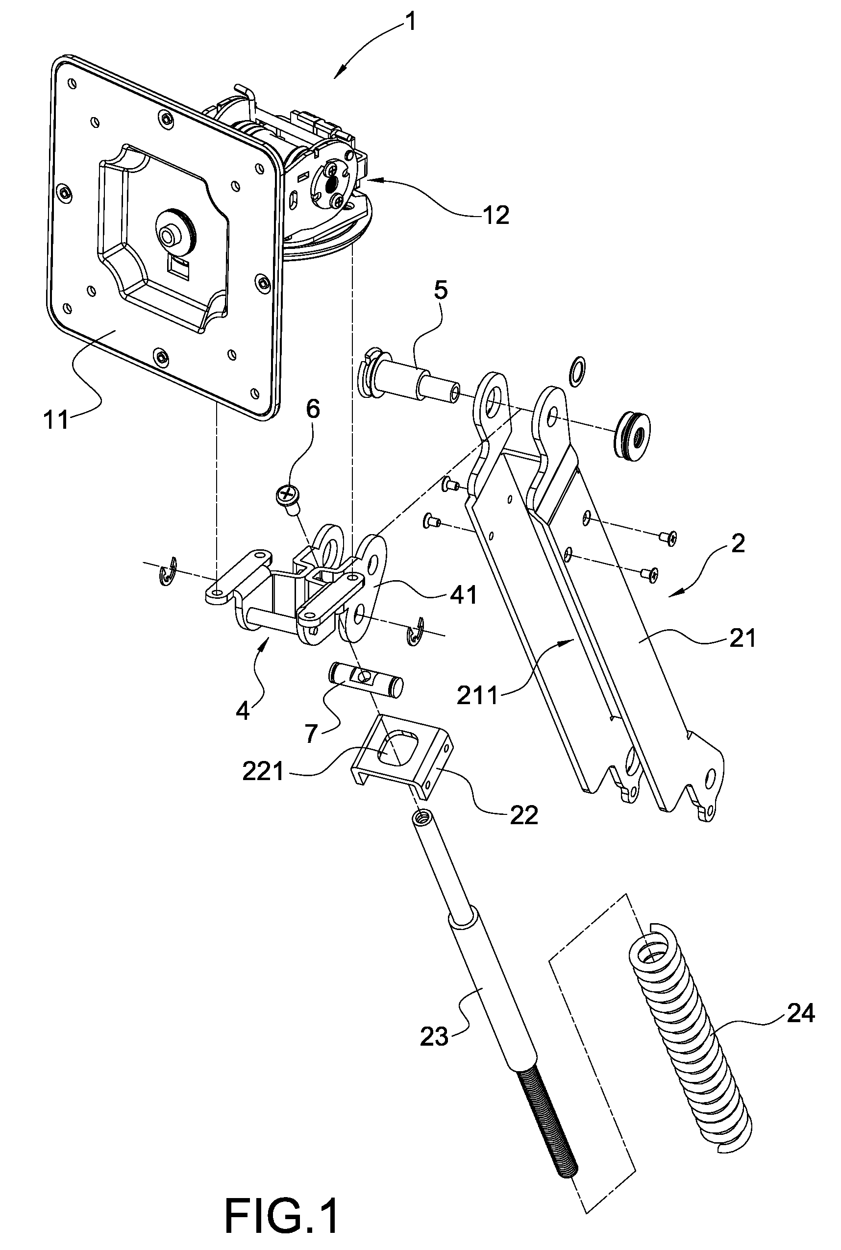
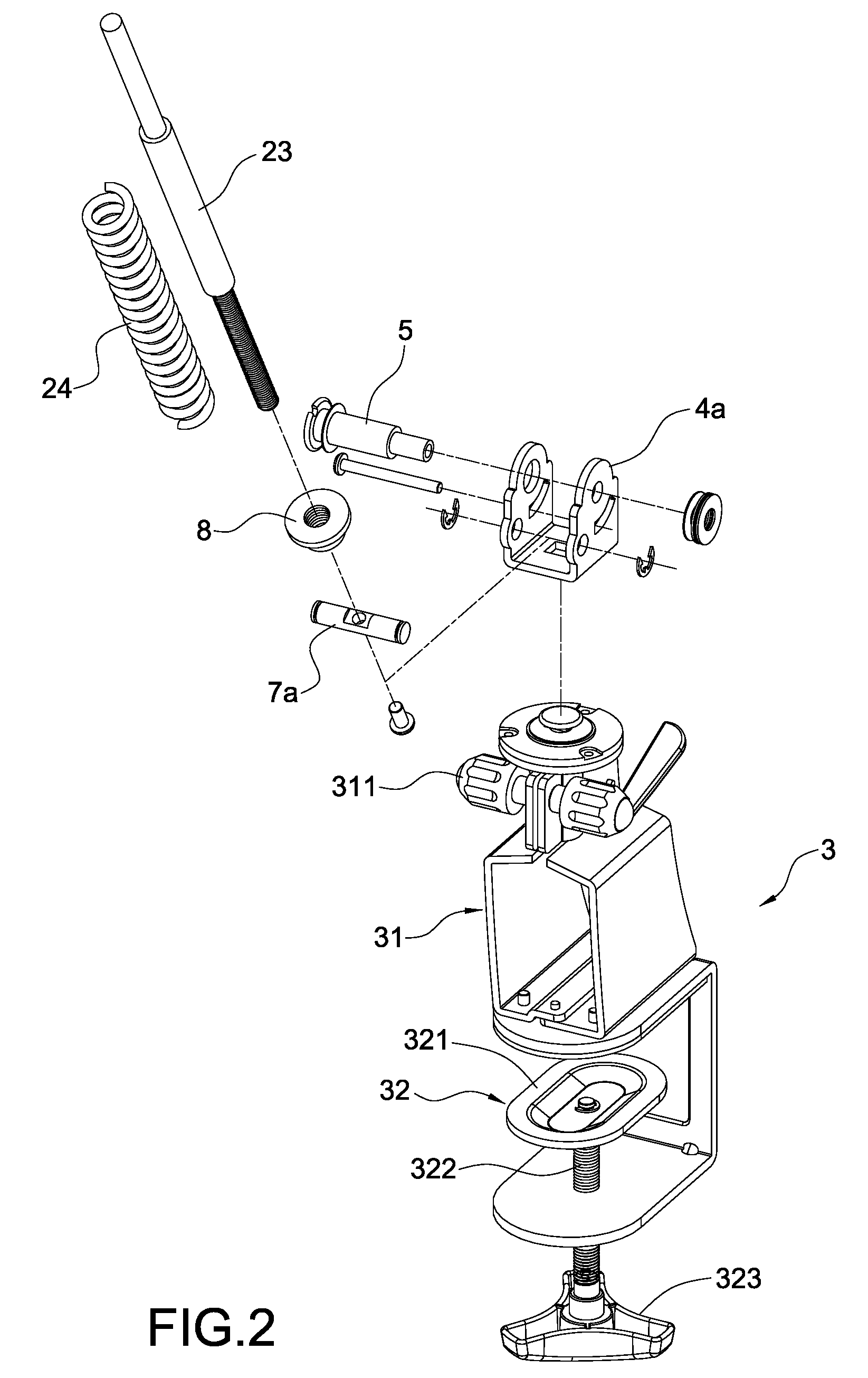
[0018]Please refer to FIG. 1 and FIG. 2 that are perspective views explosively showing the structure of the present invention. As shown in these figures, a supporting structure according to the present invention mainly includes a connecting seat 1, a fixing mechanism 2, and a fixing seat 3. The connecting seat 1, in the meantime, has a supporting plate 11 and a rotational mechanism 12. The supporting plate 11 is for connecting a display 100, as shown in FIG. 4. The rotational mechanism 12 is connected to the bottom position of the supporting plate 11. The angle of the supporting plate 11 may be adjusted under the bringing a...


PUM


Abstract

A single spring supporting device includes a connecting seat, a fixing seat, and a fixing mechanism. The connecting seat and the fixing seat are respectively connected to two sides of the fixing mechanism. The connecting seat is for connecting a display, while the fixing seat is for fixing the supporting device to a position. The fixing mechanism further has a holder, in which a blocking plate and a fixing rod are arranged. One side of the fixing rod is arranged through the blocking plate. An elastic element, in addition, is arranged through the fixing rod, another side of which is rotationally connected to a nut. The display is adjusted to an optimally viewing angle by in cooperation with the blocking plate to control a telescoping operation of the elastic element and by adjusting the relative angles of the fixing mechanism with respect to the connecting seat and the fixing seat.

Description

BACKGROUND OF THE INVENTION[0001]1. Field of the Invention[0002]The present invention generally relates to a supporting device, in particular, to a support structure for supporting a display.[0003]2. Description of Prior Art[0004]Following the rapid development of science and technology, various electronic devices invented accordingly have brought different conveniences to people's living. A current display, in particular, may provide all kinds of messages, through data being transmitted and controlled by computer to thereby provide people with instant information. In order to match the arrangement of different positions of a display, a supporting device is provided and connected to the back thereof for fixing it to different positions and for fixing it with an optimally viewing angle through connected operation.[0005]A prior supporting device, commonly seen in current market, includes a connecting seat, a fixing seat, and a fixing mechanism. The connecting seat and the fixing seat ...

Claims


Application Information

Patent Timeline
Patent Type & Authority Patents(United States)
IPC IPC(8): E04G3/00
CPCF16M11/04F16M11/10F16M11/2014F16M11/2092F16M13/02F16M13/022F16M13/08F16M2200/022F16M2200/063Y10S248/919Y10S248/922
Inventor HUANG, SHIAN-NUNGHSIEH, MING-TSUNG
Owner HUANG SHIAN NUNG
Why Eureka
Try Eureka