Device for the elastic mounting of a hydraulic unit in a motor vehicle braking system on a vehicle

a technology for a braking system and a hydraulic unit, which is applied in the direction of suspensions, washers, shock absorbers, etc., can solve the problem of unnecessary separation of components for securing the position of the uni

Active Publication Date: 2009-03-31
ROBERT BOSCH GMBH
View PDF30 Cites 53 Cited by
  • Summary
  • Abstract
  • Description
  • Claims
  • Application Information

AI Technical Summary

Benefits of technology

[0008]With one embodiment of the apparatus, a three-point mounting of the unit is created, in which the elastomer elements, received on the second leg of the mounting bracket, can be associated with one end face of the unit, which contributes to minimizing the requisite installation space for the unit in the vehicle.

Problems solved by technology

Separate components for securing the position of the unit are therefore unnecessary.

Method used


Image

  • Device for the elastic mounting of a hydraulic unit in a motor vehicle braking system on a vehicle
  • Device for the elastic mounting of a hydraulic unit in a motor vehicle braking system on a vehicle
  • Device for the elastic mounting of a hydraulic unit in a motor vehicle braking system on a vehicle

Examples


Embodiment Construction

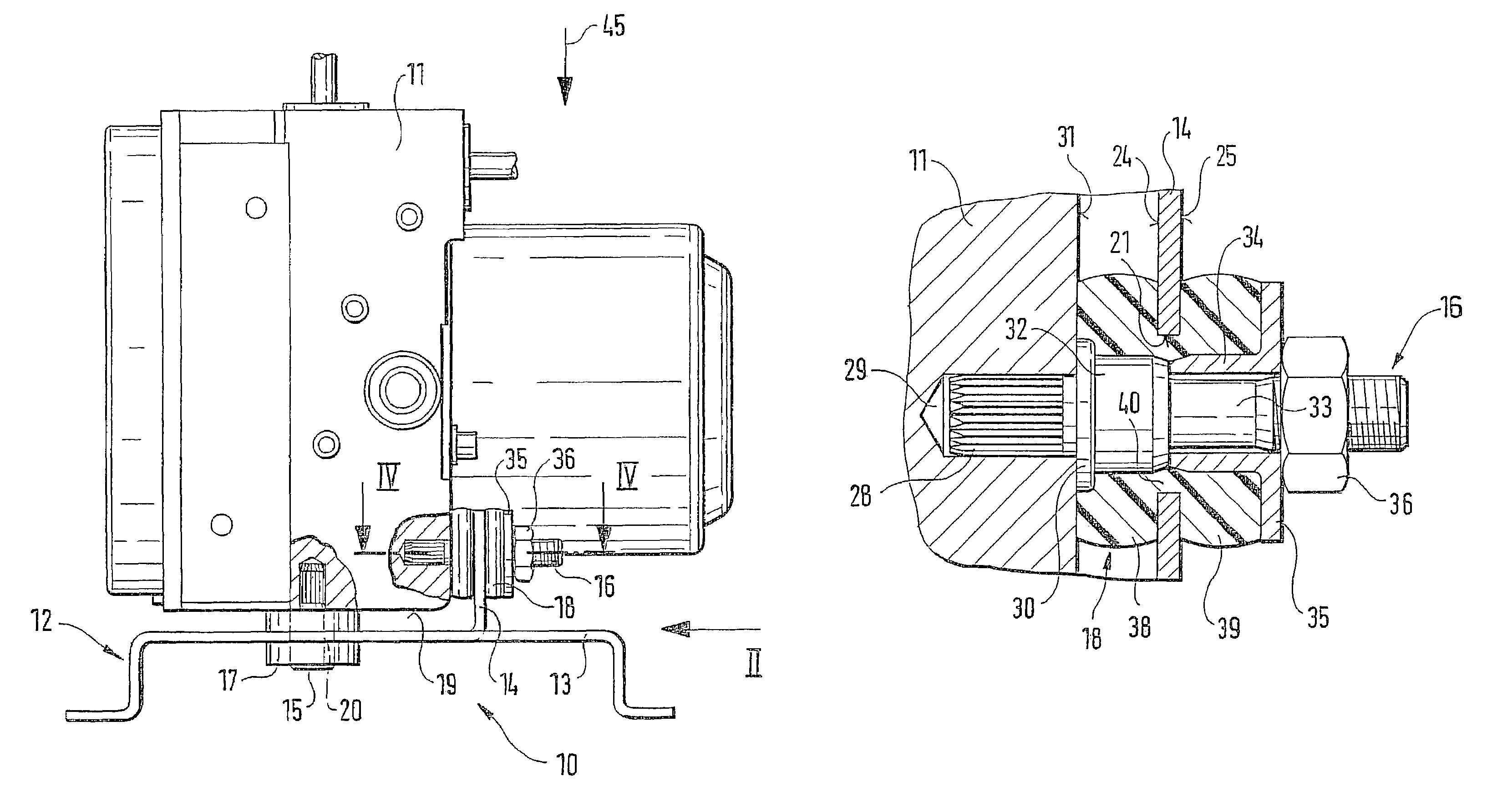
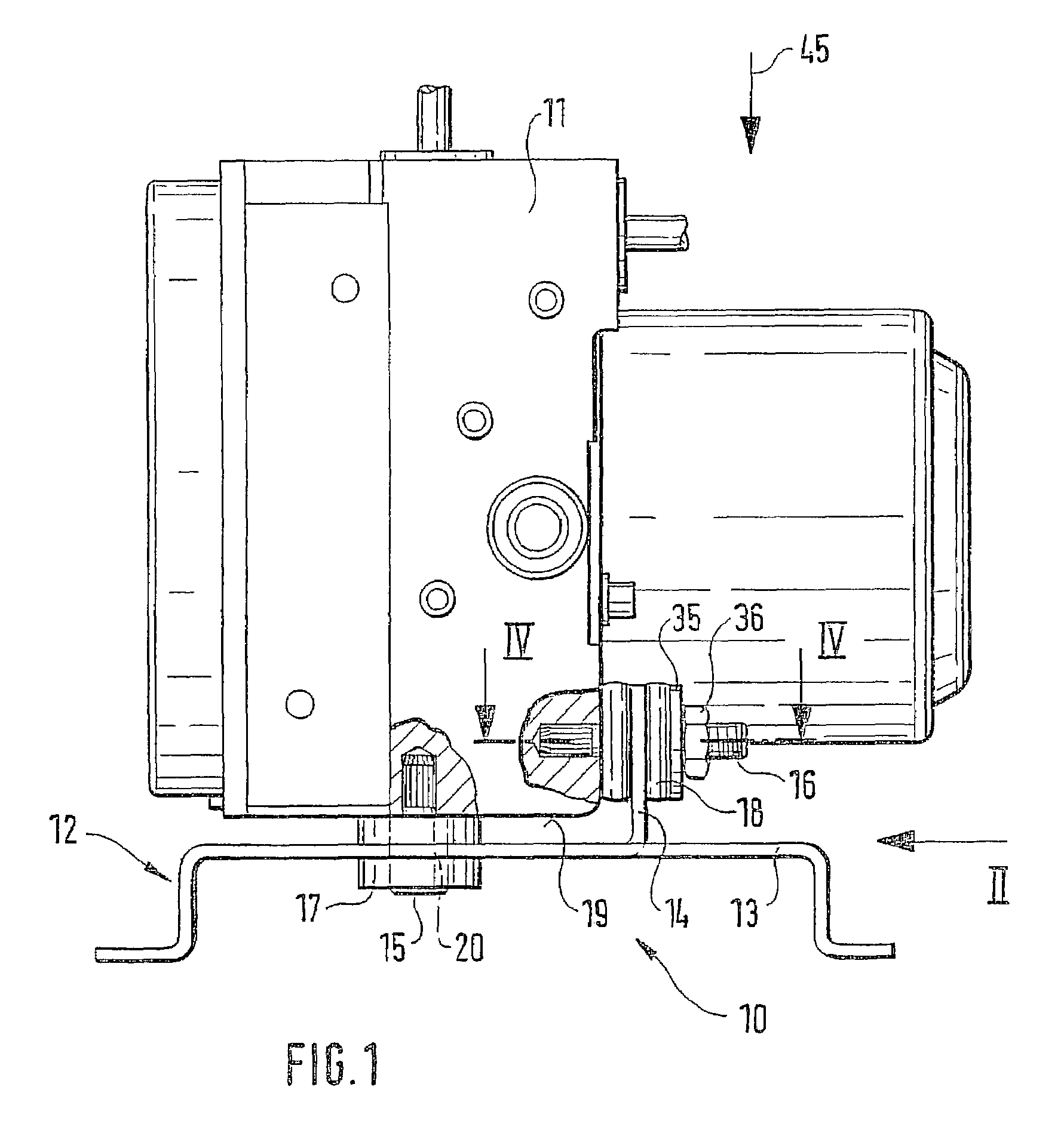
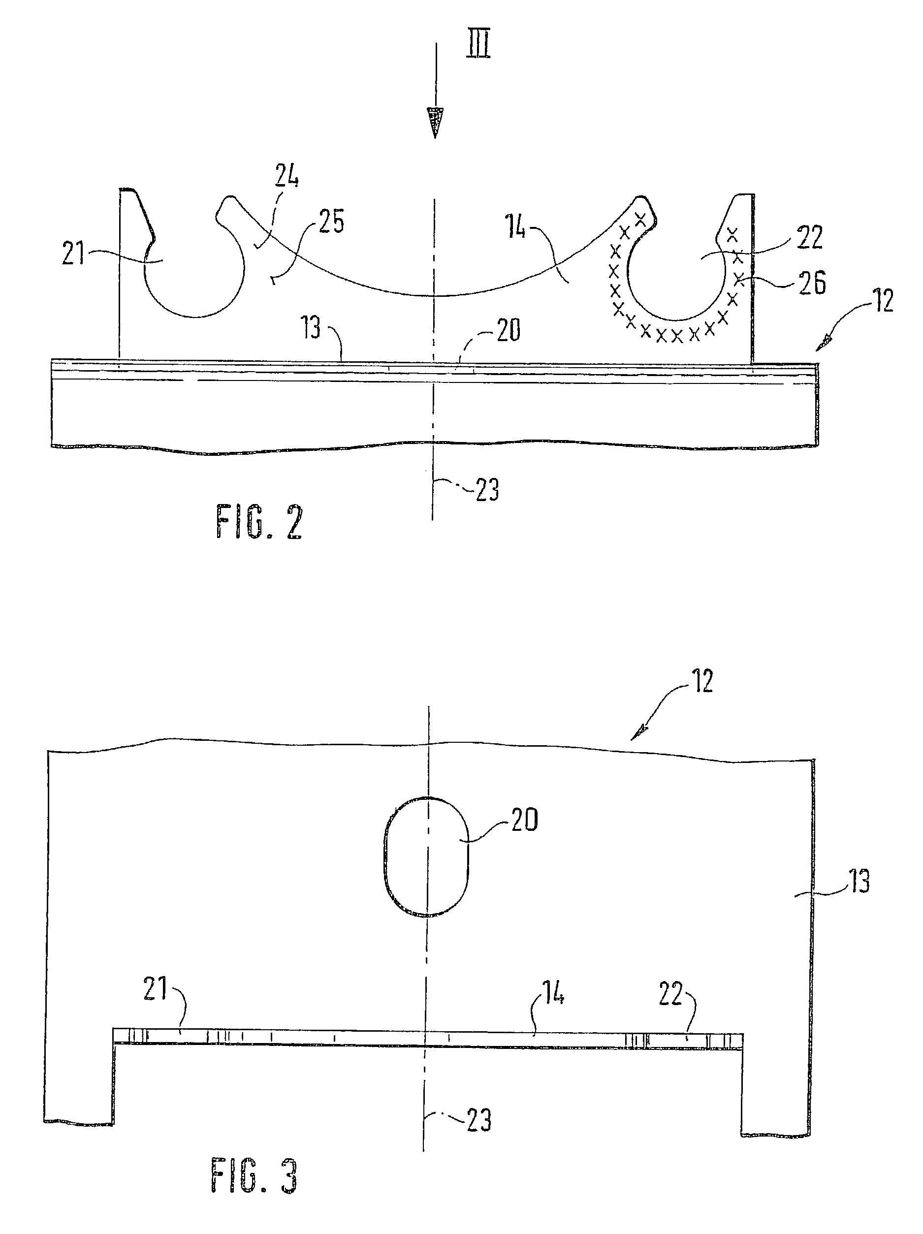
[0017]An apparatus 10, shown in FIG. 1 of the drawing, for elastic mounting of a hydraulic unit 11 of a vehicle brake system, not otherwise shown, has a mounting bracket 12, which as is only suggested schematically in the drawing is solidly connected to a body of a vehicle. The mounting bracket 12 has two legs 13 and 14, extending perpendicular to one another, on which the unit 11 is supported by means of elastomer elements 17 and 18 through which respective bolts 15 and 16 pass. The bolt 15 located on the underside 19 of the unit 11 is press-fitted over part of its length into this unit and passes through the hollow-cylindrical elastomer element 17. The latter is snapped into an opening 20, in the form of an oval or elliptical oblong slot, in the first leg 13 that extends parallel to the underside 19 of the mounting bracket 12, the mounting bracket being embodied as a shaped sheet-metal part. Two spaced-apart recesses 21 and 22 are embodied on the second leg 14, which protrudes upw...


PUM


Abstract

A hydraulic unit is elastically supported by means of elastomer elements, through which bolts pass, on two legs of a mounting bracket that extend perpendicular to one another. The leg of the mounting bracket has recesses, open counter to the mounting direction of the unit, for receiving the elastomer element. With clamping means disposed on the bolt, the elastomer element is axially shortened and pressed against both the recess and side faces, located on either side of the recess, of the leg of the mounting bracket. With the shortened elastomer element, a positive and nonpositive engagement with the leg of the mounting bracket is achieved.

Description

CROSS-REFERENCE TO RELATED APPLICATIONS[0001]This application is a 35 USC 371 application of PCT / DE 01 / 02265 filed on Jun. 19, 2001.BACKGROUND OF THE INVENTION[0002]1. Field of the Invention[0003]The invention is directed to an improved resilient mounting device and more particularly to such a device for elastically mounting a hydraulic unit of a vehicle brake system.[0004]2. Description of the Prior Art[0005]One apparatus of the type with which this invention is concerned is already known (German Patent Disclosure DE 197 24 177 A1), which has a mounting bracket with one rib at the bottom and two legs protruding at right angles from the rib and spaced apart from one another. One bearing shell open at the top is embodied in each of the legs. The rib, conversely, is provided with an upward-oriented bolt. A hydraulic unit of a vehicle brake system is inserted into the mounting bracket from above. In the process, the bolt, with the interposition of a bushlike elastomer element, engages ...

Claims


Application Information

Patent Timeline
Patent Type & Authority Patents(United States)
IPC IPC(8): F16M13/00B60T8/36B60T17/00F16F1/373F16F15/08
CPCB60T8/3685F16F1/3732Y10T403/4958Y10T403/4941B60T17/00
Inventor SCHLITZKUS, MICHAELSCHWARZ, RAINERWEH, ANDREAS
Owner ROBERT BOSCH GMBH
Why Eureka
Try Eureka