Cable tension device having a tension adjustable function

Inactive Publication Date: 2009-03-31
JIA HSIN PRESS CAST IND
View PDF9 Cites 27 Cited by
  • Summary
  • Abstract
  • Description
  • Claims
  • Application Information

AI Technical Summary

Benefits of technology

[0008]Another objective of the present invention is to provide a cable tension device, wherein when the cable is tightened to a determined extent by rotation of the movable seat, the force applied by the cable on the ratchet unit is greater than that applied by the engaging board and the push board on the ratchet unit, so that the engaging board is pushed and deflected by the ratchet unit to pass by the ratchet unit, and the movable seat performs an idle rotation, thereby preventing the cable fro

Problems solved by technology

However, the user easily applies an excessive force on the movable seat to tighten the cable too excessively by successive

Method used


Image

  • Cable tension device having a tension adjustable function
  • Cable tension device having a tension adjustable function
  • Cable tension device having a tension adjustable function

Examples


Embodiment Construction

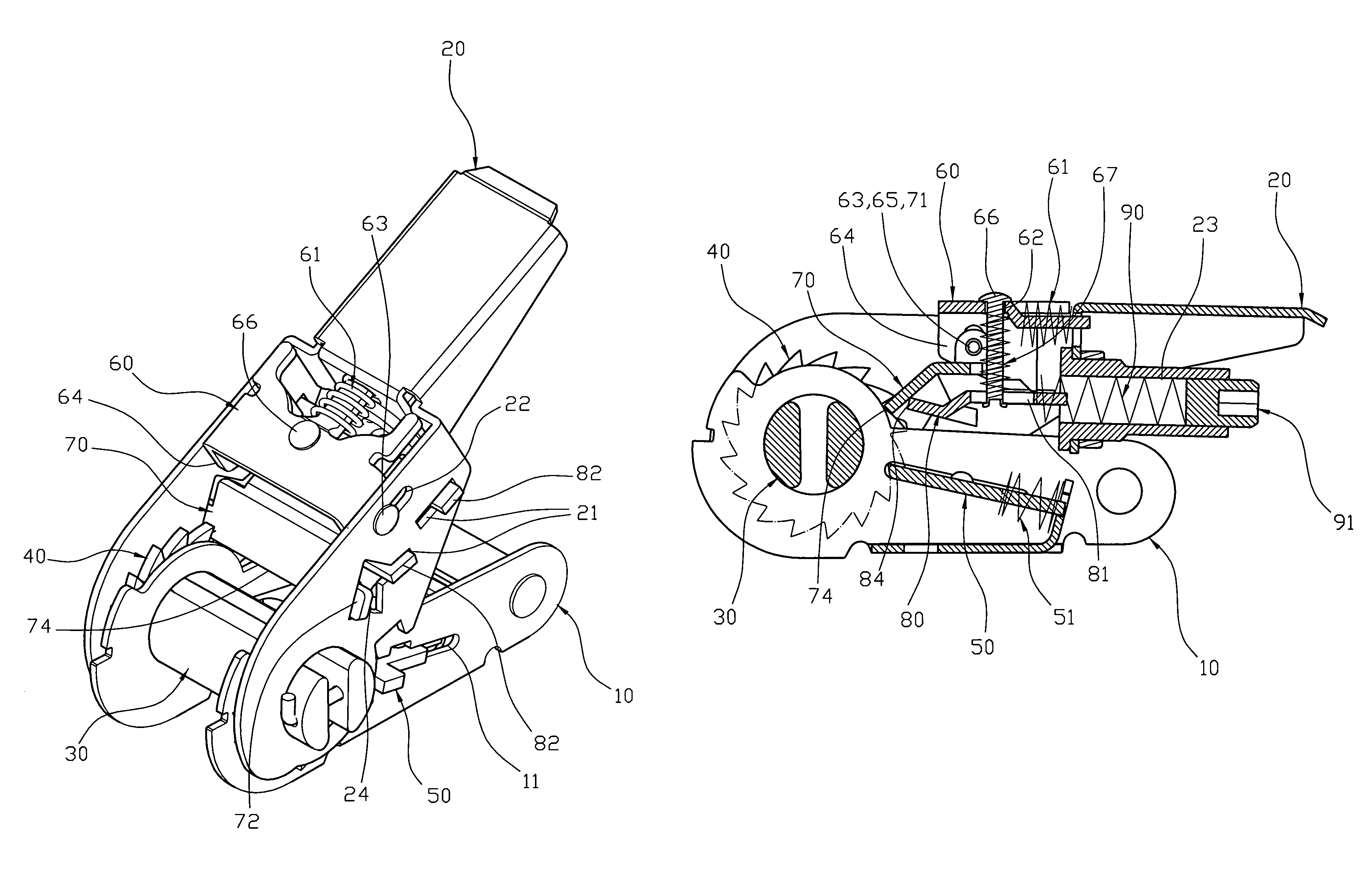
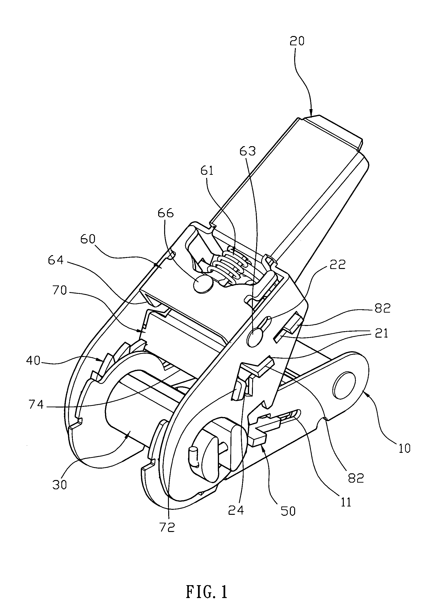
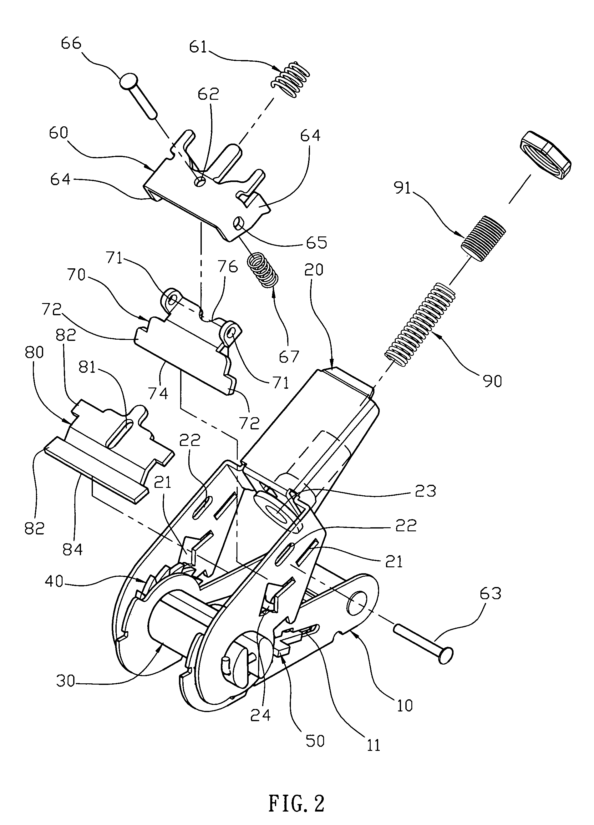
[0021]Referring to the drawings and initially to FIGS. 1-4, a cable tension device in accordance with the preferred embodiment of the present invention comprises a fixing seat 10, a rotation shaft 30 rotatably mounted on the fixing seat 10, a ratchet unit 40 secured on the rotation shaft 30 to rotate the rotation shaft 30, a movable seat 20 rotatably mounted on the rotation shaft 30, a safety locking plate 50 movably mounted on the fixing seat 10 and detachably engaged with the ratchet unit 40 to allow the ratchet unit 40 to rotate forward in one direction only, a control member 60 movably mounted on the movable seat 20, an engaging board 70 pivotally connected with the control member 60 and detachably engaged with the ratchet unit 40 to drive the ratchet unit 40 to rotate forward in the one direction only, a push board 80 movably mounted on the movable seat 20 and rested on the engaging board 70 to push the engaging board 70 to deflect forward in an inclined angle, a compression sp...


PUM

PropertyMeasurementUnit
Forceaaaaaaaaaa
Tensionaaaaaaaaaa

Abstract

A cable tension device includes a fixing seat, a rotation shaft, a ratchet unit, a movable seat, a safety locking plate, a control member, an engaging board, a push board, a compression spring, and a tension adjustment knob. Thus, when the cable is tightened to a determined extent by rotation of the movable seat, the force applied by the cable on the ratchet unit is greater than that applied by the engaging board and the push board on the ratchet unit, so that the engaging board is pushed and deflected by the ratchet unit to pass by the ratchet unit, and the movable seat performs an idle rotation, thereby preventing the cable from being tightened too excessively.

Description

BACKGROUND OF THE INVENTION[0001]1. Field of the Invention[0002]The present invention relates to a cable tension device and, more particularly, to a cable tension device for tightening a cable to bind a cargo.[0003]2. Description of the Related Art[0004]A conventional cable tension device comprises a fixing seat, a rotation shaft rotatably mounted on the fixing seat to wind and unwind a cable, a ratchet unit secured on the rotation shaft to rotate the rotation shaft, a movable seat rotatably mounted on the rotation shaft, an locking plate mounted on the fixing seat and detachably engaged with the ratchet unit to allow the ratchet unit to rotate forward in one direction only, an elastic engaging board mounted on the movable seat and detachably engaged with the ratchet unit to drive the ratchet unit to rotate forward in the one direction only.[0005]In operation, when the movable seat is rotatable relative to the fixing seat forward, the engaging board is rotatable with the movable sea...

Claims


Application Information

Patent Timeline
IPC IPC(8): B21F9/00
CPCB65B13/025Y10T24/2117Y10T24/2113Y10T24/2175Y10T24/2121
Inventor LIN, CHIA-SHENG
Owner JIA HSIN PRESS CAST IND
Why Eureka
Try Eureka