Stepped time based servo pattern and head

a servo pattern and stepped time technology, applied in the direction of maintaining head carrier alignment, digital recording, instruments, etc., can solve the problems of creating positioning errors that distort the reading or writing of data tracks, and achieve the effect of more efficiency

Inactive Publication Date: 2009-03-31
ADVANCED RES
View PDF20 Cites 110 Cited by
  • Summary
  • Abstract
  • Description
  • Claims
  • Application Information

AI Technical Summary

Problems solved by technology

In such time based servo patterns, any errors in the servo data create positioning errors that distort the reading or writing of the data tracks.

Method used


Image

  • Stepped time based servo pattern and head
  • Stepped time based servo pattern and head
  • Stepped time based servo pattern and head

Examples


Embodiment Construction

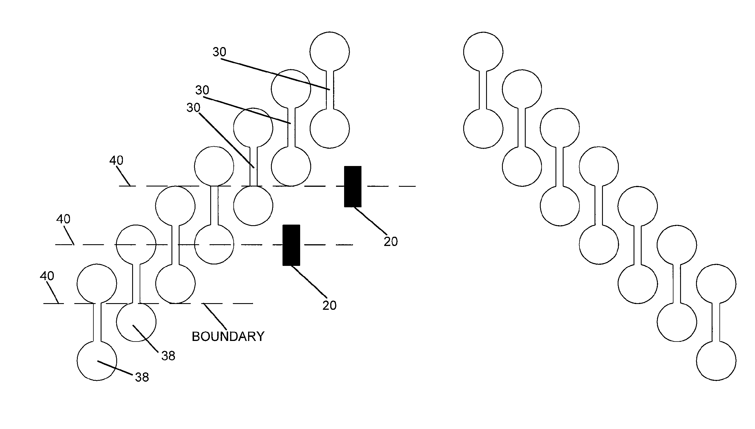
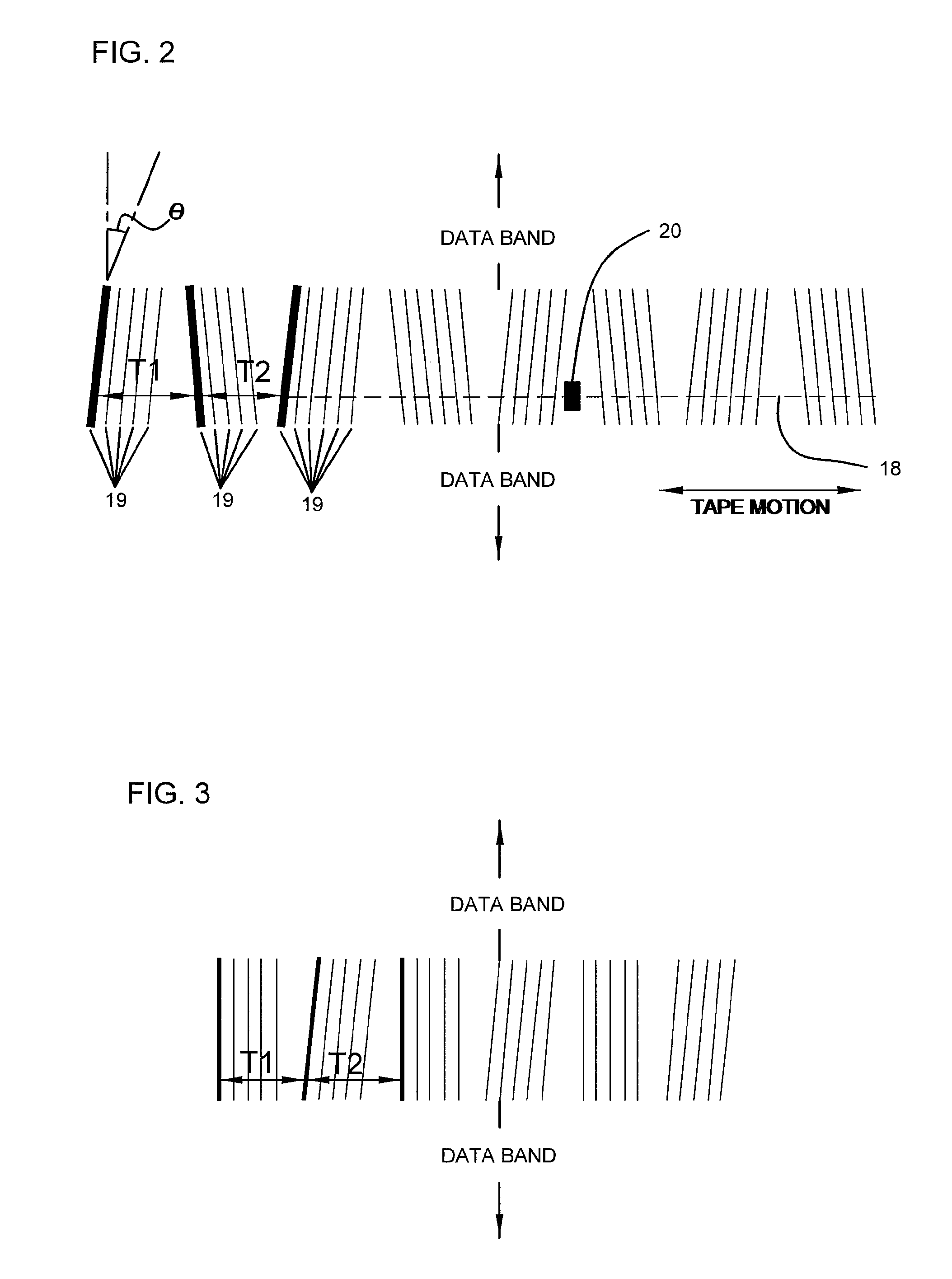
[0023]The present invention relates to apparatuses and methods used in manufacturing magnetic tape. More specifically, the present invention relates to a method of writing a servo pattern on magnetic tape so as to minimize errors in the servo pattern, the heads used to write such servo data, and the magnetic tape manufactured with such heads. Errors in the servo pattern may be minimized by synthesizing the slanted transitions in a time based servo pattern using servo write gaps that are perpendicular to the tape motion. In so minimizing errors, distortion in the reading and / or writing of the data tracks can be prevented.

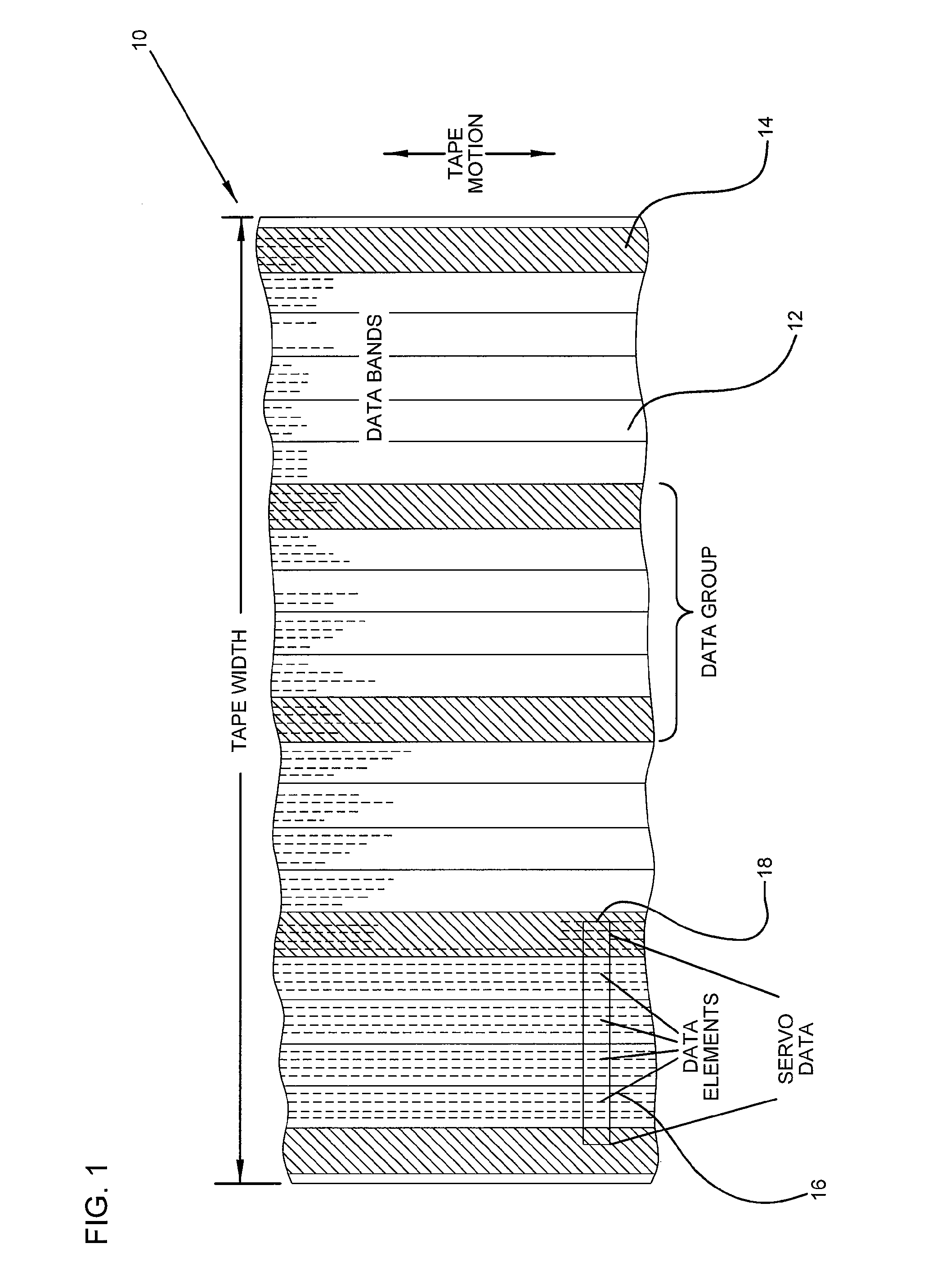
[0024]FIG. 1 shows a magnetic tape 10 having data bands or data tracks 12 and servo bands or servo tracks 14. The data tracks 12 are the portions of tape 10 to which data elements 16 would be written and from which data elements 16 would be read. Similarly, servo tracks 14 include servo data 18 which are written into the servo track during manufacture of the magnetic...


PUM

PropertyMeasurementUnit
angleaaaaaaaaaa
magneticaaaaaaaaaa
widthaaaaaaaaaa

Abstract

The present invention relates to apparatuses and methods used in manufacturing magnetic tape. More specifically, the present invention relates to a method of writing a servo pattern on magnetic tape so as to minimize errors in the servo pattern, the heads used to write such servo data, and the magnetic tape manufactured with such heads. Errors in the servo pattern may be minimized by synthesizing the slanted transitions in a time based servo pattern using servo write gaps that are perpendicular to the tape motion. In so minimizing errors, distortion in the reading and / or writing of the data tracks can be prevented.

Description

CROSS-REFERENCE TO RELATED APPLICATION(S)[0001]The present non-provisional patent application claims the benefit of U.S. provisional patent application Ser. No. 60 / 545,022, entitled “STEPPED TIME BASED SERVO PATTERN AND HEAD,” filed on Feb. 17, 2004, the subject matter of which is hereby incorporated by reference herein in its entirety.TECHNICAL FIELD[0002]The present application relates to a method of synthesizing the slanted transitions in a time based servo pattern using servo write gaps that are perpendicular to the tape motion.BACKGROUND OF THE INVENTION[0003]Magnetic tape as a data storage medium requires the ability effectively to write and read data to data tracks of the magnetic tape; many such data tracks typically extend linearly along the length of the tape and, in part, define tape data storage density. In recent years, much higher track densities have been achieved in tape through the inclusion of a dynamic track following servo system. In linear multi-channel tape sys...

Claims


Application Information

Patent Timeline
Patent Type & Authority Patents(United States)
IPC IPC(8): G11B5/09G11B21/02G11B5/584
CPCG11B5/584G11B5/59638
Inventor DUGAS, MATTHEW P.SCHWARZ, THEODORE A.
Owner ADVANCED RES
Why Eureka
Try Eureka