Method and apparatus for layer 2 multicast traffic management

a multicast traffic and layer 2 technology, applied in the field of communication and networking, can solve problems such as poor efficiency

Active Publication Date: 2009-03-31
GARRETTCOM
View PDF12 Cites 47 Cited by
  • Summary
  • Abstract
  • Description
  • Claims
  • Application Information

AI Technical Summary

Problems solved by technology

In comparison, unicasting sends a separate copy to each ...

Method used


Image

  • Method and apparatus for layer 2 multicast traffic management
  • Method and apparatus for layer 2 multicast traffic management
  • Method and apparatus for layer 2 multicast traffic management

Examples


Embodiment Construction

[0022]Problems with Conventional IGMP and IGMP Snoopinq

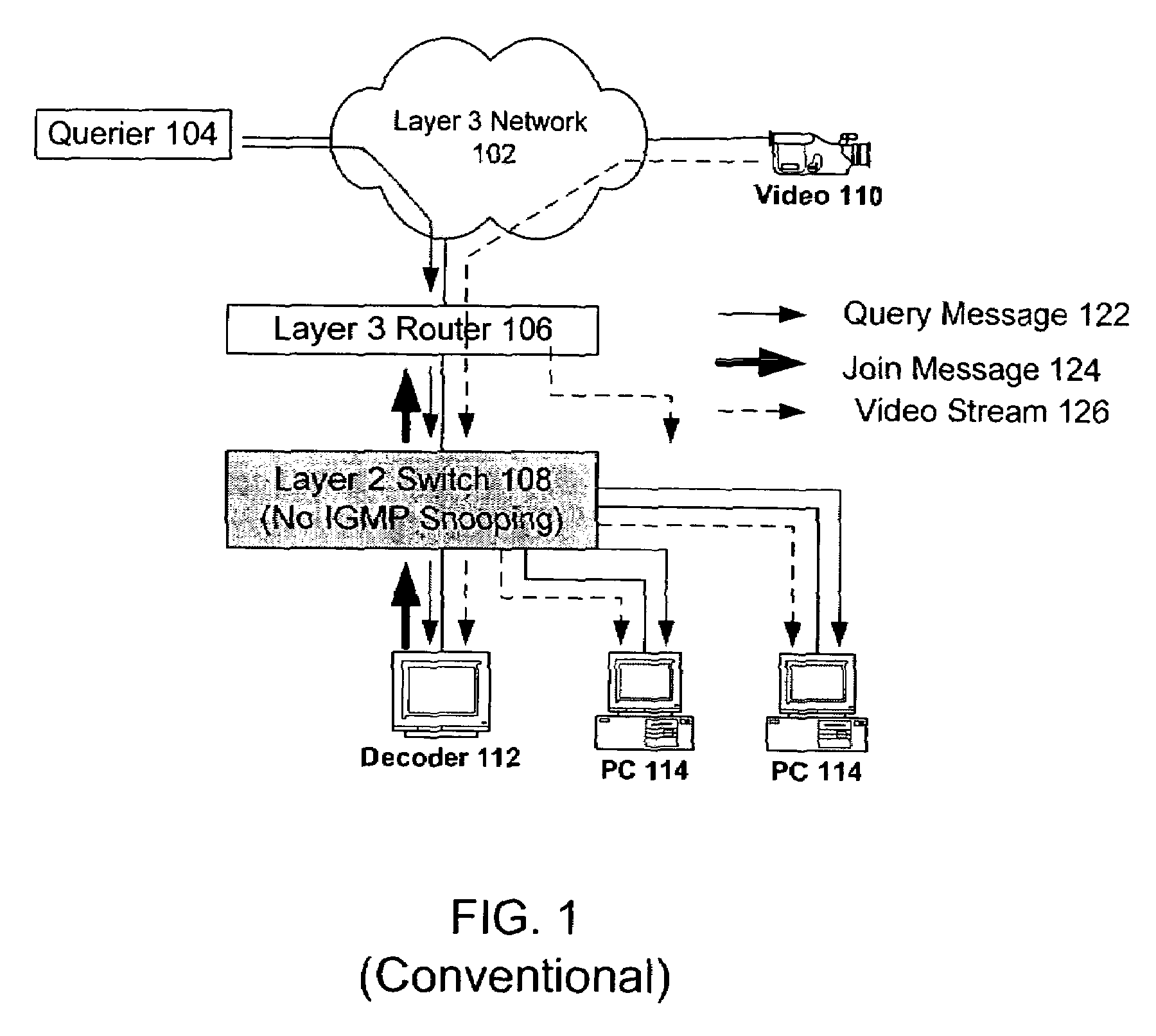
[0023]FIG. 1 depicts multicasting in an example conventional network having a layer 3 router 106 and a layer 2 switch 108 without IGMP snooping. In this example network, the querier device 104 and the multicast vsource 110 are coupled to the layer 3 router 106 by way of a layer 3 (for example, IP) network 102. Here, the multicast source 110 is a video source which outputs a video stream 126. A video decoder 122 which is to receive the multicast video stream 126 is on the layer 2 switch 108.

[0024]As depicted, the querier device 104 sends a query message 122 to discover the members of a multicast group. After being forwarded by the router 106, the query message 122 is received by the video decoder 112 (and by the PCs 114).

[0025]The video decoder 112 responds to the query message 122 by sending a join report message 124 to the router 106. The router 106 communicates the group membership information to the querier 104 and to the oth...


PUM


Abstract

One embodiment pertains to a switching device which is configured to provide multicast traffic management in a layer 2 network without layer 3 devices A specific embodiment relates to a method of implementing IGMP multicasting in a layer 2 network. IGMP packets are snooped by multiple switches in the layer 2 network. IGMP query messages are generated by each of the multiple switches. IGMP join report messages are forwarded by each of the multiple switches to all ports on which a querier is present. Other embodiments are also disclosed.

Description

CROSS-REFERENCE TO RELATED APPLICATIONS[0001]The present application claims the benefit of U.S. provisional patent application No. 60 / 763,569, filed Jan. 31, 2006, by inventors Dileep Sivasankaran, Frank S. Madren, and Rajeev Garg, entitled “Method and Apparatus for Layer 2 Multicast Traffic Management,” the disclosure of which is hereby incorporated by reference.NOTICE REGARDING COPYRIGHTED MATERIAL[0002]A portion of the disclosure of this patent document contains material which is subject to copyright protection. The copyright owner has no objection to the facsimile reproduction by anyone of the patent document or the patent disclosure as it appears in the Patent and Trademark Office file or records, but otherwise reserves all copyright rights whatsoever.BACKGROUND OF THE INVENTION[0003]1. Field of the Invention[0004]The present application relates generally to communications and networking. More particularly, the present application relates to multicasting in networks.[0005]2. De...

Claims


Application Information

Patent Timeline
IPC IPC(8): H04L12/56H04J1/16
CPCH04L12/18H04L45/04H04L45/16H04L45/66
Inventor SIVASANKARAN, DILEEPMADREN, FRANK S.GARG, RAJEEV
Owner GARRETTCOM
Why Eureka
Try Eureka