LED illumination apparatus

a technology of illumination apparatus and led light, which is applied in the direction of lighting and heating apparatus, fixed installation, semiconductor devices for light sources, etc., can solve the problems of low heat resistance, high cost of preparing different molds for different components, and requiring a relatively complicated manufacturing process, so as to shorten the time for developing, reduce the cost of making molds, and simplify the process of manufacturing and assembling lamps.

Inactive Publication Date: 2009-04-07
PYROSWIFT HOLDING CO LIMITED
View PDF8 Cites 166 Cited by
  • Summary
  • Abstract
  • Description
  • Claims
  • Application Information

AI Technical Summary

Benefits of technology

[0008]Therefore, the present invention is to provide an LED illumination apparatus that is extruded integrally with a lamp housing by an aluminum material to simplify the processes of manufacturing and assembling the lamp. Furthermore, it is not necessary to produce different molds for different models of the illumination apparatuses according to their specifications, powers or lumens, and thus effectively lowering the cost for making molds and shortening the time for developing and manufacturing the lamps, since the lamp housing can be cut and divided according to actual needs.

Problems solved by technology

Further, the LED lamps come with a low heat resistance, and thus a heat sink is usually required for dissipating the heat produced by each LED lamp.
However, the traditional LED illumination apparatus still has the following drawbacks on its usage.
Since the lamp housing, the partition and the heat sink of the LED module are made separately, not only incurring a high cost for preparing different molds for different components, but also requiring a relatively complicated manufacturing process and greatly increasing the manufacturing and assembling costs.
Further, it is necessary to produce different molds for different models of illumination apparatuses according to their specifications, powers or lumens, and thus further increasing the cost for making molds and extending the time for developing and manufacturing the lamps.
The traditional LED illumination apparatus only uses heat pipes for heat dissipation, but the heat pipe has a very limited surface area in contact with the LED lamp, and thus the quantity of dissipated heat is also limited.

Method used


Image

  • LED illumination apparatus
  • LED illumination apparatus
  • LED illumination apparatus

Examples


Embodiment Construction

[0017]The technical characteristics, features and advantages of the present invention will become apparent in the following detailed description of the preferred embodiments with reference to the accompanying drawings. However, the drawings are provided for reference and illustration only and are not intended for limiting the scope of the invention.

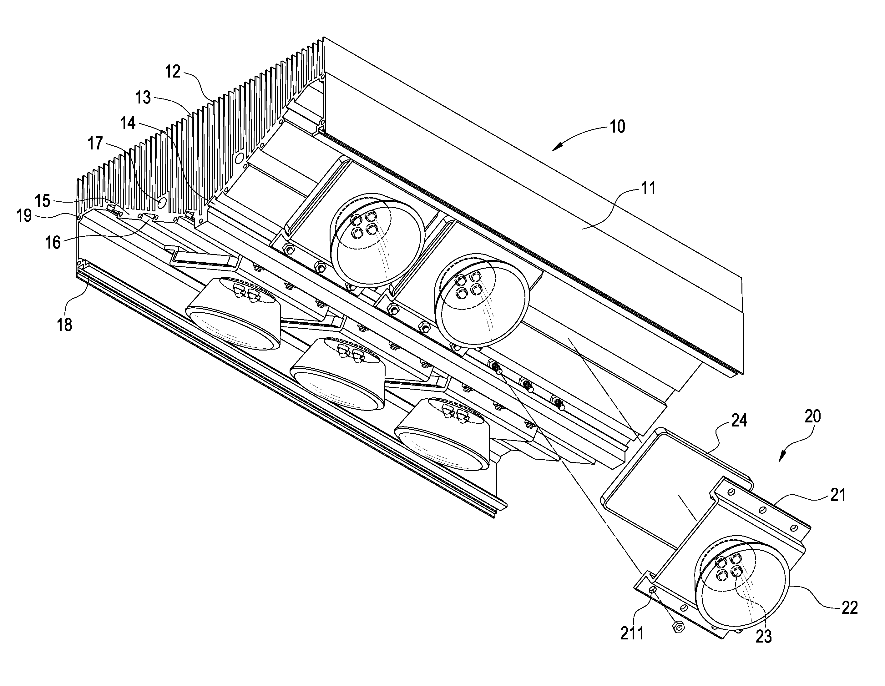
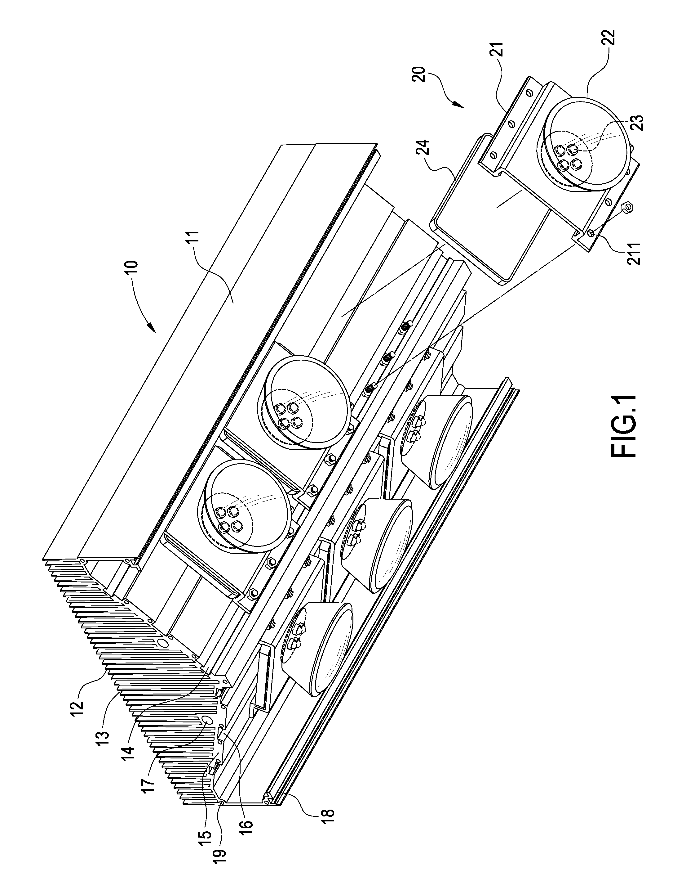
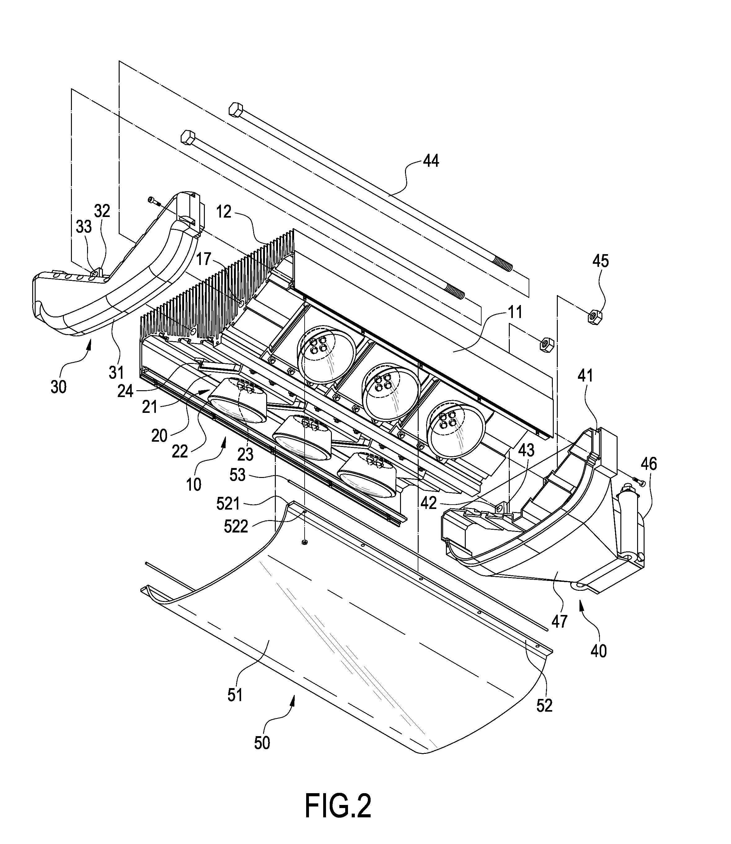
[0018]Referring to FIGS. 1 to 4 for a partial exploded view, an exploded view, a perspective view and a cross-sectional view of a lamp housing and an LED module in accordance with the present invention, an LED illumination apparatus of the invention comprises an aluminum extrusion lamp housing 10, a plurality of LED modules 20, a set of distal covers 30, 40 and a light-transmitting hood 50.

[0019]The aluminum extrusion lamp housing 10 comprises an M-shape base 11, a plurality of parallel heat sinks 12 extended upward from the top of an oblique plate of the base 11, a heat dissipating channel 13 formed between any two adjacent heat sinks 12...


PUM


Abstract

An LED illumination apparatus includes a lamp housing, an LED module, distal covers and a light-transmitting hood. The lamp housing has a base, a heat sink at the top of the base, a heat dissipating channel between two adjacent heat sinks, and a receiving portion on an internal side of the base. The LED module includes a fixing base, a lampshade on a side of the fixing base, a plurality of LED lamps in the lampshade, and a connecting portion on the fixing base and coupled to the corresponding receiving portion. Each distal cover seals the front and back of the lamp housing, and the light-transmitting hood is connected under the lamp housing, and a containing space enclosed by the lamp housing, distal cover and light-transmitting hood for installing the LED module. The invention can simplify the manufacturing processes and reduce the material cost and development time.

Description

BACKGROUND OF THE INVENTION[0001]1. Field of the Invention[0002]The present invention relates to an LED illumination apparatus, and more particularly to an LED illumination apparatus that can simplify the processes of manufacturing and assembling lamps.[0003]2. Description of Prior Art[0004]Since light emitting diodes (LEDs) feature the advantages of high brightness, power saving and long life expectancy, LEDs have been used extensively for illuminations. Several LED lamps are usually arranged and connected to a circuit board to form an LED lamp module and several LED lamp modules are connected in series or in parallel to constitute an LED module to achieve an illumination effect that meets the requirements for a large projecting area and a high brightness for outdoor illuminations, and serve as an indoor or outdoor illumination apparatus. The outdoor illumination apparatus is usually exposed to the outside over a long period of time, and thus its requirements for air tightness, wat...

Claims


Application Information

Patent Timeline
Patent Type & Authority Patents(United States)
IPC IPC(8): F21V7/20F21V29/505
CPCF21S8/086F21V15/013F21V29/004F21V29/76F21V29/75F21S2/005F21V19/001F21Y2101/02F21V15/015Y10S362/80F21W2131/103F21Y2115/10F21V29/74
Inventor WANG, PEI-CHOA
Owner PYROSWIFT HOLDING CO LIMITED
Why Eureka
Try Eureka