Data transfer system and data transfer method

a data transfer system and data transfer technology, applied in the field of data transfer methods, can solve the problems of packet loss, reduced throughput of the home agent or the mobile node of the receiving node, and reduced network efficiency, so as to prevent the degradation of radio wave strength or the like, and reduce the load on the mobile node

Inactive Publication Date: 2009-04-07
FUJITSU LTD
View PDF16 Cites 2 Cited by
  • Summary
  • Abstract
  • Description
  • Claims
  • Application Information

AI Technical Summary

Benefits of technology

[0039]It is an object of the present invention to prevent the possibility of occurrence of packet loss due to a hand over, degradation of radio wave strength, or the like.
[0041]In this data transfer method, the relay node buffers the data that is transmitted from the corresponding node which is a transmitting node, based on a request from the mobile node which is a receiving node of the data in streaming distribution or the like. The relay node transmits the buffered data to the mobile node according to a buffering data request by timing the mobile node specifies. When there is a possibility of occurrence of packet loss, the relay node initiates buffering the packet according to a request for initiating the buffering from the mobile node, and transmits the buffered packet to the mobile node according to a buffered-data transmission request from the mobile node. Thus, the packet loss can be avoided.
[0043]According to the present invention, occurrence of the packet loss due to a hand over, degradation of radio wave strength, or the like can be prevented. Furthermore, since the packet buffering is initiated according to the request for initiating the buffering from the mobile node and the packet is transferred according to the buffered-data transmission request from the mobile node, the mobile node does not need to always manage the sequence number of the received packet and a load on the mobile node is reduced.

Problems solved by technology

If there is a packet that is not received in these steps, a re-transmission processing is performed by the TCP protocol and it brings about a problem that network efficiency decreases.
Therefore, since the packet could not be received by the mobile node 1, there arises a problem that packet loss could occur.
Due to this, in the conventional method, there has been a problem that throughput of the home agent or of the mobile node of a receiving node decreases.
Further, in such a case where there exist a plurality of communication destinations and there is a communication among them using a communication application or the like that is inadequate for the buffering, since the buffering is performed for all the communication data, there has been a problem that the process becomes slower.
There has been a problem that packets which fail to be buffered due to exceeding the buffer size or missing packets due to the change of radio wave strength in a wireless network cannot be compensated in this method.

Method used


Image

  • Data transfer system and data transfer method
  • Data transfer system and data transfer method
  • Data transfer system and data transfer method

Examples


first embodiment

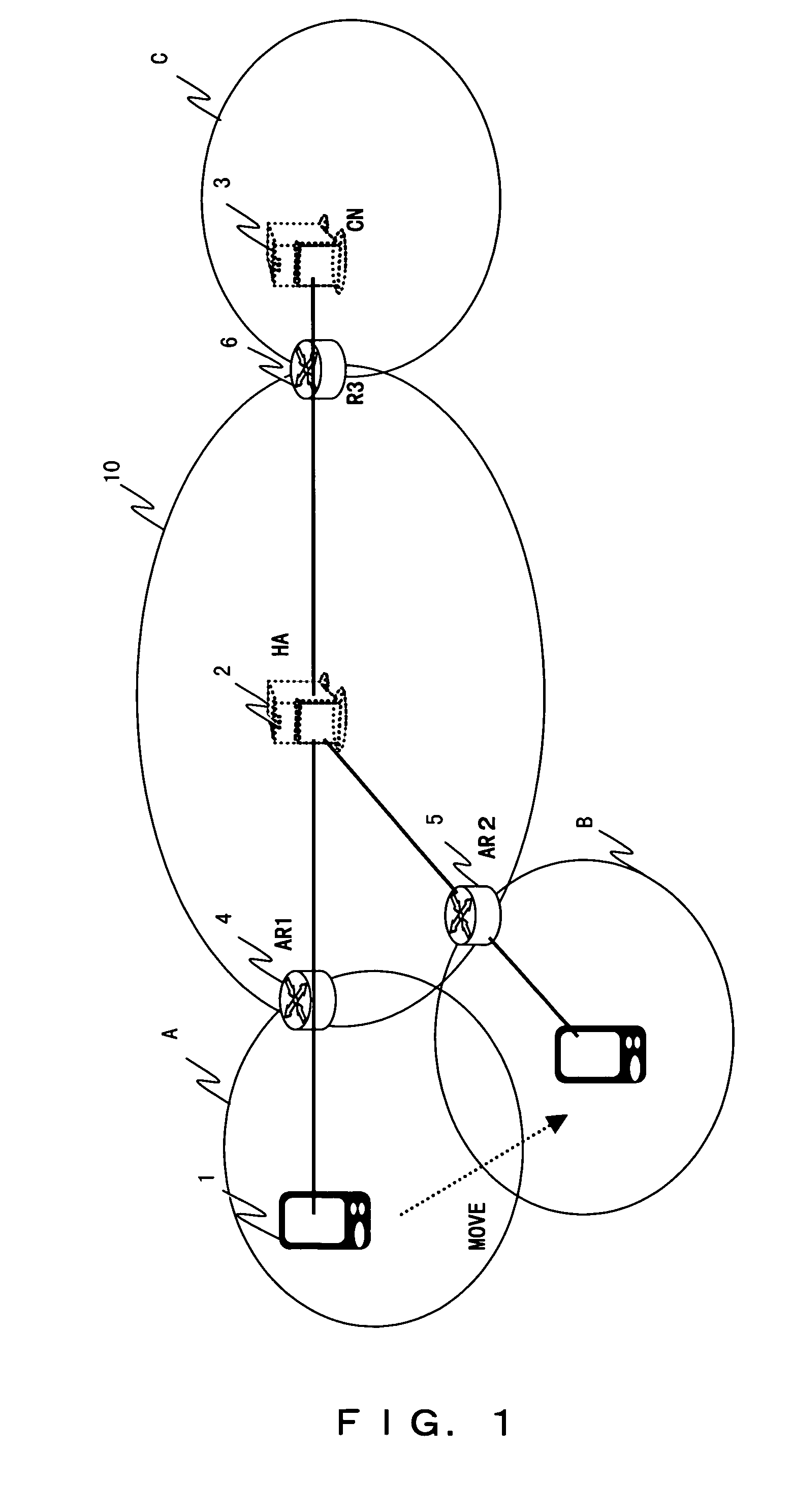
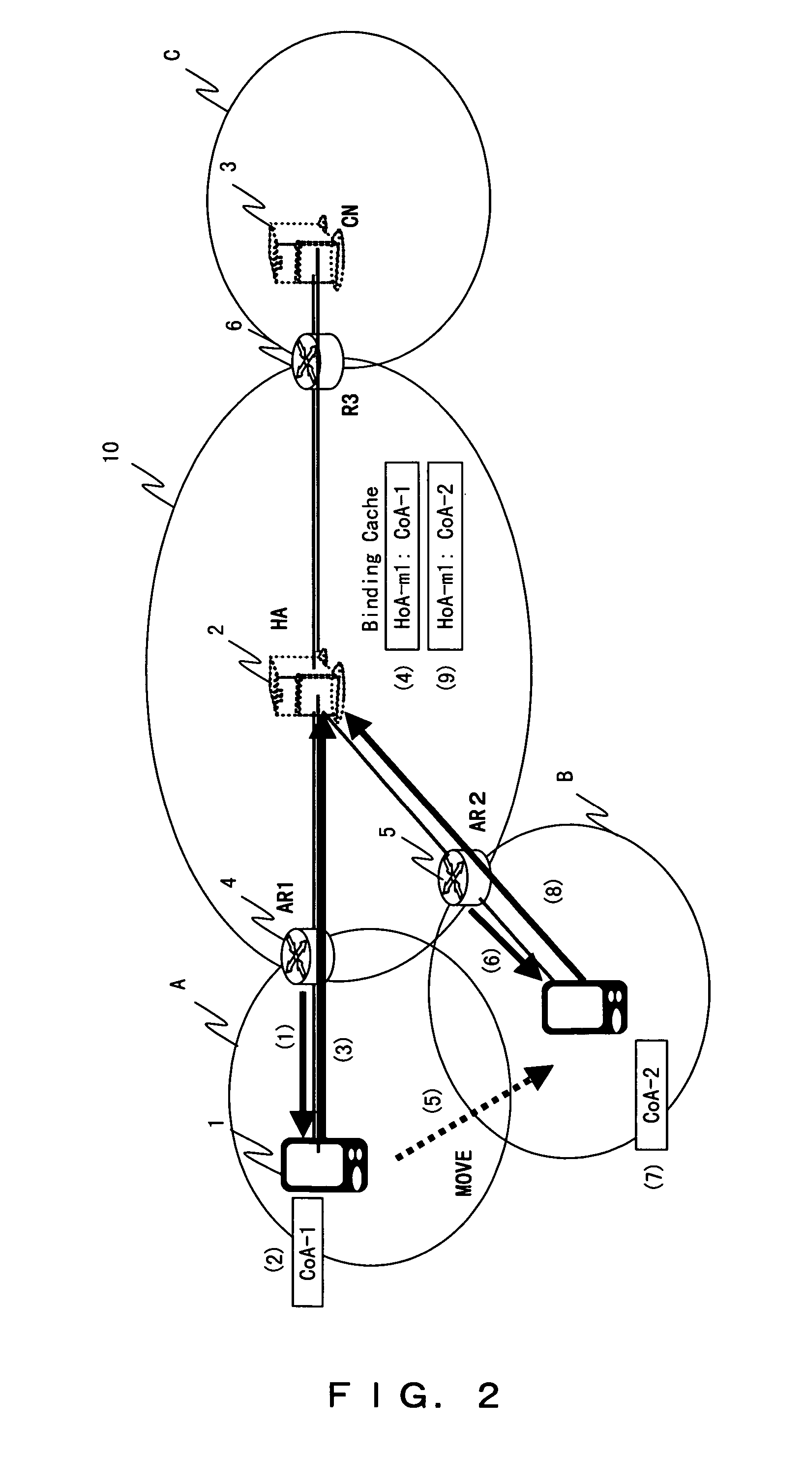
[0103]FIG. 9 is a diagram explaining a method in which a home agent of a relay node transmits a buffered packet to a mobile node by a request from the mobile node. In the same way as FIG. 1, a home agent (a mobile-supporting node, HA) 2 which is a relay node, access routers 4 and 5, and a router 6 are connected to the Internet 10. Suppose that a corresponding node (CN) 3 under a network C is transmitting data to a mobile node 1 through the relay node 2. Further, the mobile node 1 is under a wireless network A and is communicating with the corresponding node 3 through the access router 4. In practice, a plurality of mobile nodes are connected to the Internet 10 through the access router; however, to be simplified for explanation, FIG. 9 shows only a single mobile node. Furthermore, the network C is not limited to a wireless network. These also apply to the embodiments below.

[0104]The following is the method in which the home agent 2 transmits the buffered packet to the mobile node, i...

second embodiment

[0113]In this embodiment, the home agent creates a home address for transmitting and receiving the buffered packet when starting a packet buffering. In a packet transfer method according to this embodiment, a description of the system structure and the processes that are a repetition of those in the first embodiment is omitted here.

[0114]FIG. 10 is a diagram explaining a method for managing an address used for transmission and reception of the packet buffered in the home agent. Steps corresponding to numbers in parentheses in FIG. 10 are described as follows.[0115](1) The mobile node 1 transmits a buffer registration request message which requests the home agent 2 to buffer the packet. This buffer registration request message corresponds to the specified timing in step (2) of the first embodiment.[0116](2) The home agent 2 creates a buffering home address (hereafter called BHoA) for performing the buffering and initiates the process from step (2) onward in the first embodiment. As t...

third embodiment

[0118]In this embodiment, furthermore, in communication of a packet of streaming distribution, etc. transmitted from the corresponding node 3, the mobile node 1 which is a receiving node for the packet transmits to the corresponding node 3 a message including the index information which the mobile node receives from the home agent 2 to manage. In the same way as the second embodiment, since the system structure is the same as in the first embodiment, a description thereof is omitted here. In the embodiments below as well, a description of the same system structure is omitted.

[0119]FIG. 11 is a diagram explaining a method of using a code for transmission and reception of the buffered packet. In the steps indicated with parentheses in FIG. 11, steps (1) and (2) are the same as (1) and (2) in FIG. 10 respectively; therefore, a description thereof is omitted here, and steps from (3) onward will be described.[0120](3) The home agent 2 transmits and notifies the created BHoA to the mobile...


PUM


Abstract

In a data transfer method using a communications network that comprises, at least, a mobile node, a corresponding node that distributes data to the mobile node, and a relay node that relays data transfer between the mobile node and the corresponding node, the mobile node requests the relay node to initiate buffering data that is transmitted from the corresponding node. The relay node buffers data that is transmitted from the corresponding node and addressed to the mobile node. The mobile node requests the relay node to transmit the buffered data to the mobile node. The relay node transmits the buffered data to the mobile node.

Description

BACKGROUND OF THE INVENTION[0001]1. Field of the Invention[0002]The present invention relates to a data transfer method when transmitting and receiving data via a wireless communications network and a mobile node and a relay node that are used in the wireless communication network.[0003]2. Description of the Related Art[0004]FIG. 1 is a structure example of an existing network. A home agent (a mobile-supporting node, HA) 2 which is a relay node, access routers 4 and 5, and a router 6 are connected to the Internet 10. Suppose that a corresponding node (CN) 3 under a network C is transmitting data to a mobile node 1 through a relay node 2. Further, the mobile node 1 is under a wireless network A and is communicating with the corresponding node 3 through the access router 4. After the mobile node 1 becomes under a contiguous wireless network B due to the move or the like, it communicates through the access router 5.[0005]FIG. 2 is a diagram explaining the operation at the time of a han...

Claims


Application Information

Patent Timeline
Patent Type & Authority Patents(United States)
IPC IPC(8): H04W4/00H04L12/70H04L12/861H04L13/08H04W28/00H04W28/14H04W36/00H04W36/02H04W40/34H04W64/00H04W80/04H04W88/04
CPCH04W36/02H04W28/14H04W88/04
Inventor MATSUMOTO, YUJI
Owner FUJITSU LTD
Why Eureka
Try Eureka