Door or gate closing hinge

a door or gate hinge and hinge shaft technology, applied in the field of door or gate closing hinges, can solve the problem of holding the screwdriver, and achieve the effect of increasing the length of the hinge shaft, increasing the length of the first hinge part, and keeping relatively compa

Inactive Publication Date: 2009-04-14
TALPE JOSEPH
View PDF11 Cites 11 Cited by
  • Summary
  • Abstract
  • Description
  • Claims
  • Application Information

AI Technical Summary

Benefits of technology

[0004]An object of the present invention is now to provide a new type of self-closing hinges which comprise a torsion spring, the tension of which can be adjusted more easily, i.e. without having to hold the entire tension of the torsion spring when adjusting the tension, and which can be kept relatively compact.
[0006]In the lock according to the invention, the moment exerted by the torsion spring on the first hinge part, in other words the spring tension, can be easily adjusted by rotating the screw-like element by means of a screwdriver or a spanner. The screw threaded portion on the screw-like element provides for a connection between the coupling element and the first hinge part which maintains the coupling element in position with respect to the first hinge part and which enables moreover to adjust this position without having to disconnect the coupling element from the first hinge part. The tension of the torsion spring is therefore always taken up by the first hinge part, even when adjusting this tension by rotating the screw-like element. Moreover, since the tension of the torsion spring is adjusted indirectly by rotating the coupling element by means of the screw threaded portion on the screw-like element, a smaller force has to be exerted by means of the screwdriver or the spanner onto the screw-like element than the force which has to be exerted onto the torsion spring itself to increase the tension thereof. The angular displacement of the torsion spring will indeed be smaller than the corresponding angular displacement of the screw-like element. A further advantage of the hinge according to the invention is that the adjustment system with coupling element and screw-like element can be kept relatively compact.
[0008]An advantage of this embodiment is that the screw-like element can be arranged in a direction parallel to the rotation axis of the hinge shaft so that the tension of the torsion spring can be adjusted from the upper side of the hinge. Such an embodiment enables for example to mount the first hinge part within a vertical tube element of the door or gate whilst still enabling an adjustment of the spring tension in the mounted state of the hinge without having to drill a lateral hole in the tube element.
[0010]An advantage of this embodiment is that the coupling element can be rotated as much as desired by means of the screw-like element, i.e. the number of rotations of the coupling element and thus of the torsion spring are not limited by the adjustment system.
[0012]Due to the fact that in the hinge according to the invention the adjustment mechanism can be kept relatively compact, this preferred embodiment offers the advantage that the first hinge part and all the components of the hinge enclosed thereby can be mounted in a tubular element mounted against the door or gate or even in a tubular vertical frame member of the door or gate itself. The advantage of mounting the first hinge part in a tubular vertical element is that the self-closing system is vandal proof and hidden from view. The interior of the vertical frame member offers further a long cavity so that the length of the first hinge part, and especially the length of the torsion spring, can be increased without achieving an aesthetically not acceptable hinge. By being free to choose the length of the torsion spring, this length (i.e. the number of windings) can be selected in view of the desired spring properties. Moreover, it is possible to increase also the length of the hinge shaft and to add one or more additional torsion springs underneath the first torsion spring between the hinge shaft and the first hinge part to increase the spring tension for example when the hinge is applied to a larger and heavier door or gate.

Problems solved by technology

A drawback of such an adjustment system is however that, when depressing the head of the hinge shaft, the screwdriver has to be held very strongly and a large force has to be exerted thereon in order to be able to increase the tension of the torsion spring.

Method used


Image

  • Door or gate closing hinge
  • Door or gate closing hinge
  • Door or gate closing hinge

Examples


Embodiment Construction

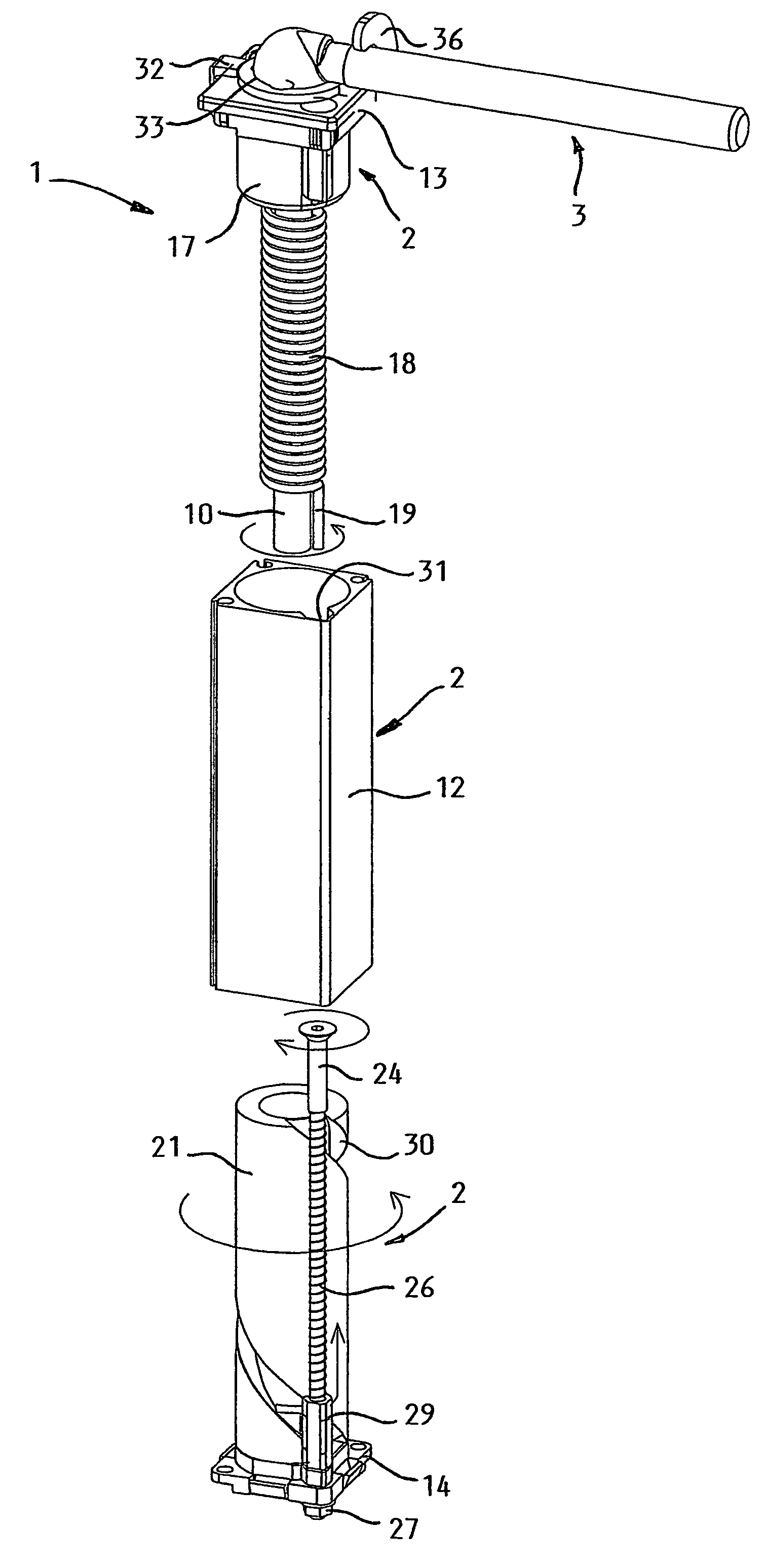
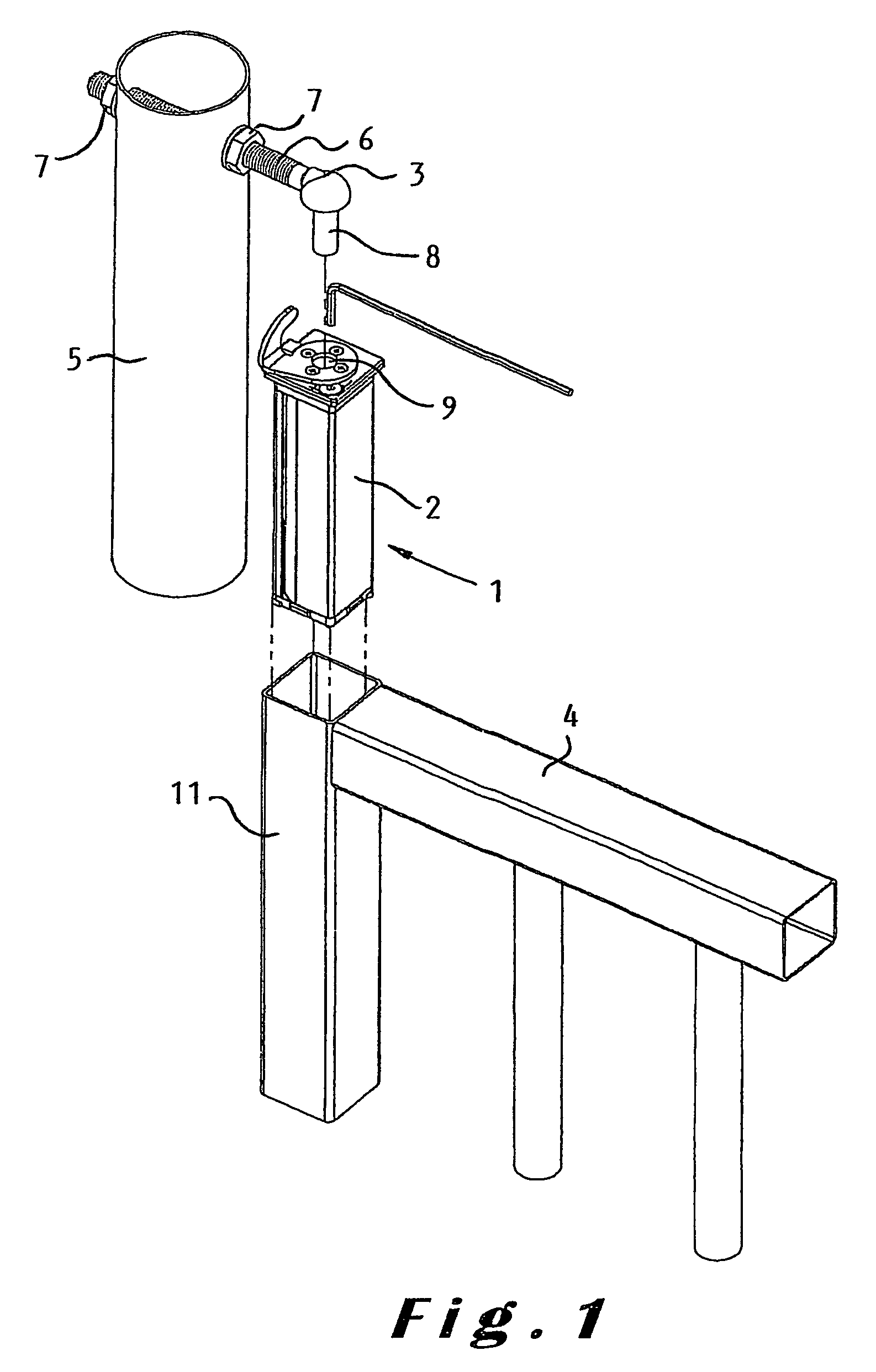
[0019]The adjustable self-closing hinge 1 illustrated in FIG. 1 comprises a first hinge part 2 arranged to be mounted to a door or gate and a second hinge part 34 arranged to be mounted to a vertical support, in particular to a pole 5.

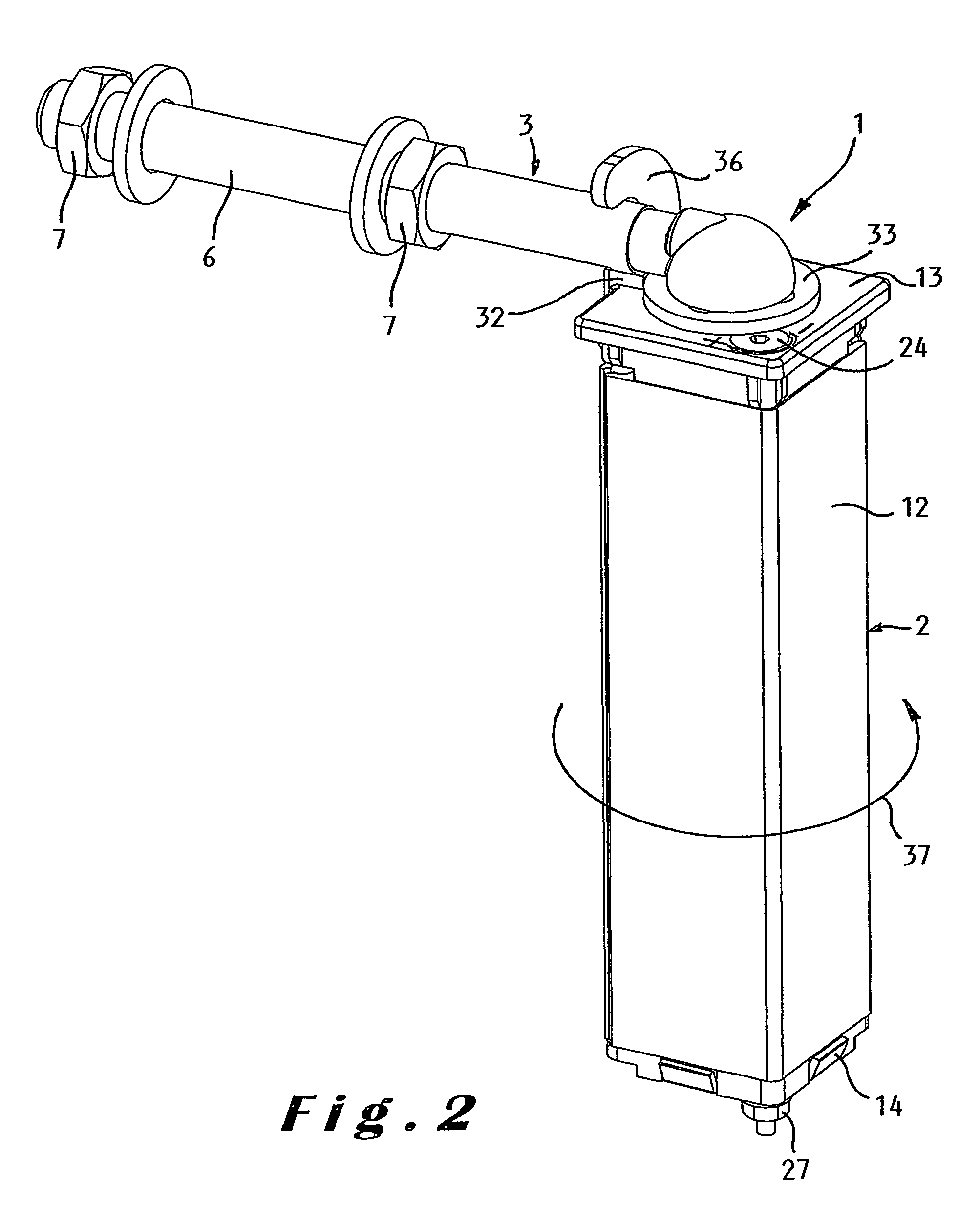
[0020]The second hinge part 3 is generally L-shaped. One leg of the L-shape is formed by a bolt portion 6 applied through two opposite holes in the pole and fixed to the pole 5 by means of two nuts 7, one on each side of the pole 5. The other leg of the L-shaped hinge part 3 is a cylindrical shaft 8 which fits in a cylindrical hole 9 provided, as explained hereinafter, in the upper side of the actual hinge shaft 10 received in the first hinge part 2.

[0021]The first hinge part 2 has a tubular shape so that it can be mounted in a vertical tubular member 11 of the door or gate 4. In the mounted state, the first hinge part 2 is thus hidden from view. A further advantage of mounting the first hinge part in the tubular gate member is that the hinge is more v...


PUM


Abstract

The adjustable self-closing hinge (1) comprises a first hinge part (2), a second hinge part (3), a hinge shaft (10), a torsion spring (18) having a first end (19) fixed with respect to the first hinge part (2) and a second end (20) fixed with respect to the hinge shaft (10) to exert a moment onto the first hinge part, and means for adjusting the moment exerted by the torsion spring on the first hinge part. These adjusting means comprise a coupling element (21) which is interposed between the first end (19) of the torsion spring (18) and the first hinge part (2) and which is rotatably mounted in the first hinge part, and a screw-like element (24) which is rotatably mounted in the first hinge part (2) and which is arranged to cooperate with the coupling element (21) to rotate the coupling element with respect to the first hinge part so as to adjust the moment exerted by the torsion spring on the first hinge part.

Description

BACKGROUND OF THE INVENTION[0001]The present invention relates to a gate or door closing hinge comprising a first hinge part, a second hinge part, a hinge shaft rotatably mounted about a first rotation axis in the first hinge part and connecting the first hinge part to the second hinge part, a torsion spring having a longitudinal axis coinciding substantially with said first rotation axis and having a first end fixed with respect to the first hinge part and a second end fixed with respect to the hinge shaft to exert a door or gate closing moment onto the first hinge part, and means for adjusting the moment exerted by the torsion spring on the first hinge part.[0002]Hinges comprising a torsion spring for closing the door or gate against which they are mounted are known. When assembling the hinges, the torsion spring is pre-tensioned so that the door or gate has to be opened against a predetermined spring tension. In practice, there exist moreover systems for adjusting the tension of ...

Claims


Application Information

Patent Timeline
Patent Type & Authority Patents(United States)
IPC IPC(8): E05F1/02E05F1/12
CPCE05F1/1215Y10T16/53862Y10T16/53988Y10T16/5995Y10T16/538627Y10T16/5386
Inventor TALPE, JOSEPH
Owner TALPE JOSEPH
Why Eureka
Try Eureka