Attachment for fuel injectors in a fuel delivery system

a fuel delivery system and fuel injector technology, applied in the direction of fuel injection apparatus, machine/engine, feed system, etc., can solve the problems of increasing the weight and cost of the overall system, unsatisfactory system noise,

Inactive Publication Date: 2009-04-14
MILLENNIUM INDS
View PDF31 Cites 51 Cited by
  • Summary
  • Abstract
  • Description
  • Claims
  • Application Information

AI Technical Summary

Problems solved by technology

One drawback of such direct injected systems, however, is that the sandwiched arrangement of the fuel injector causes undesirable noise in the system.
While such an arrangement may reduce the noise in the system, it requires additional components (e.g., the O-ring and the clip), which in turn increases both the weight and cost of the overall system and the corresponding manufacturing process.

Method used


Image

  • Attachment for fuel injectors in a fuel delivery system
  • Attachment for fuel injectors in a fuel delivery system
  • Attachment for fuel injectors in a fuel delivery system

Examples


Embodiment Construction

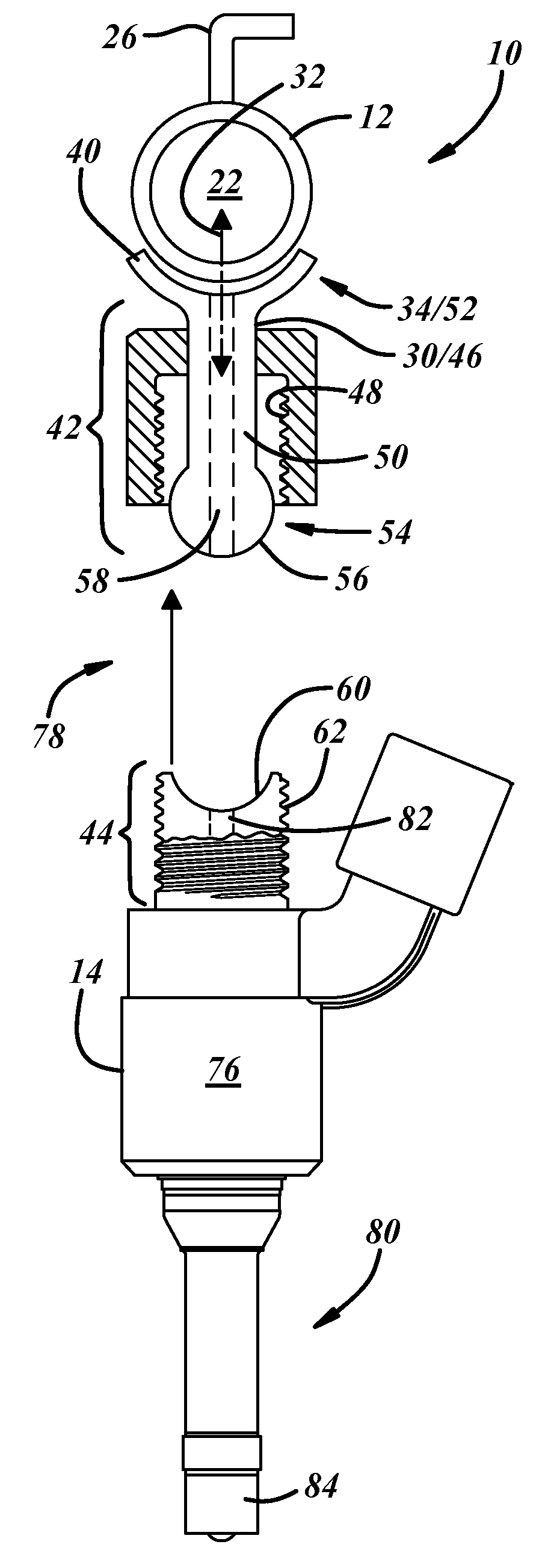
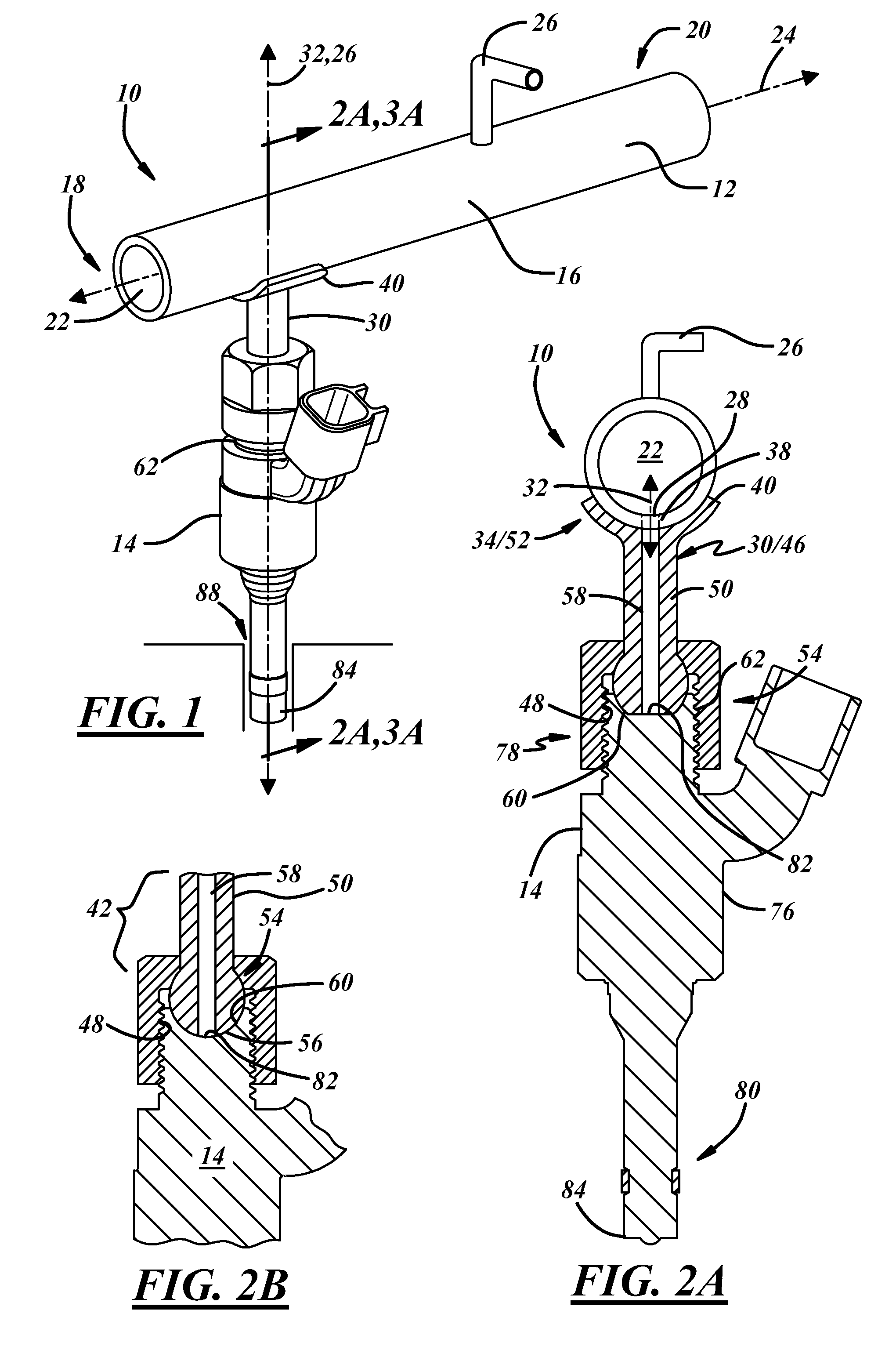
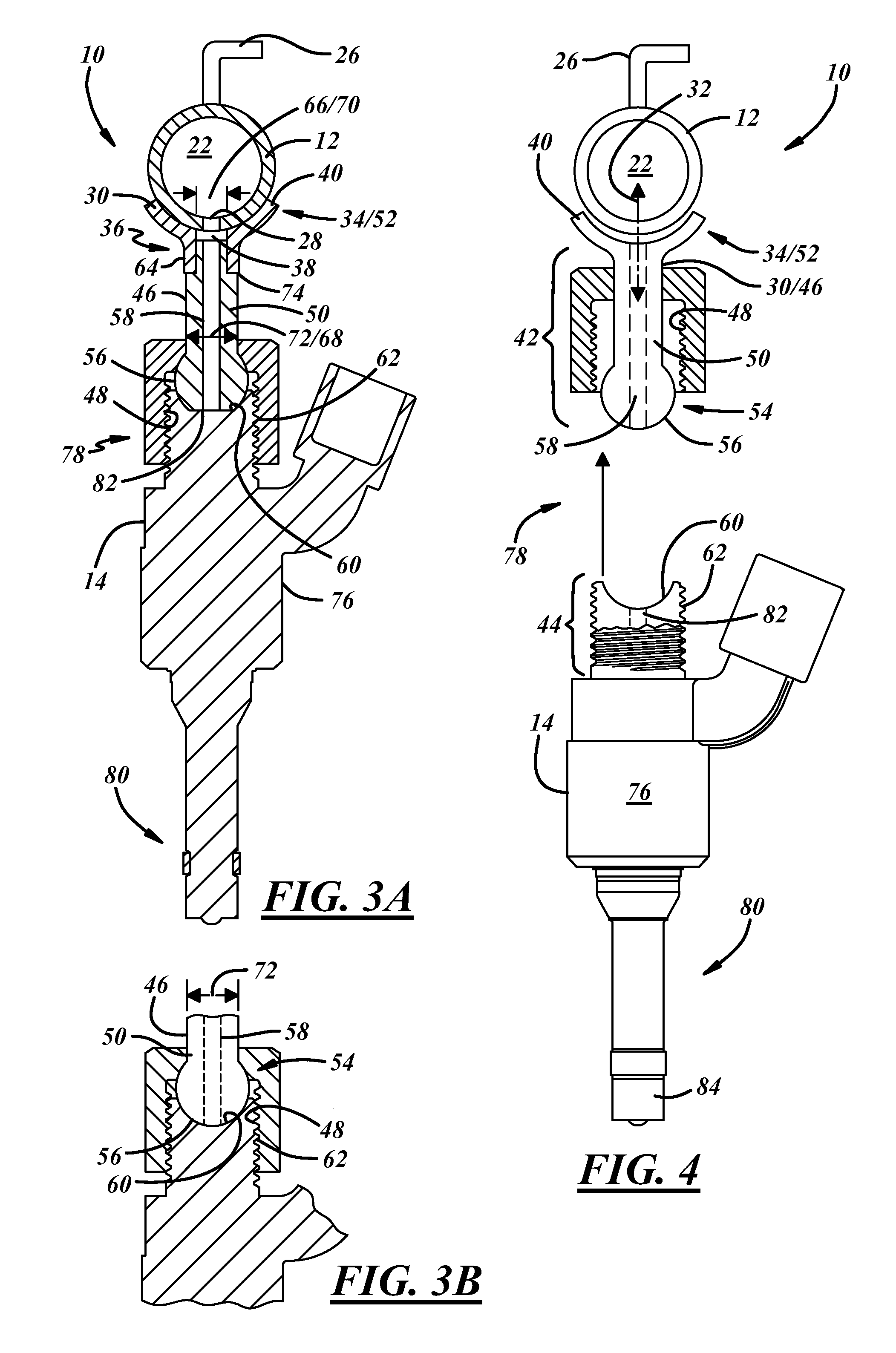
[0016]Referring now to the drawings wherein like reference numerals are used to identify identical components in the various views, FIG. 1 illustrates one exemplary embodiment of a fuel delivery system 10. Fuel delivery system 10 generally includes a fuel rail 12 and a fuel injector 14.

[0017]As shown in FIG. 1, fuel rail 12 includes a body 16 having a first end 18, a second end 20 and a fluid passageway 22 extending therebetween. Body 16 further defines a longitudinal axis 24 extending therethrough from first end 18 through second end 20. In the illustrated exemplary embodiment, fuel rail 12 is of a one-piece construction having a circular cross-section. It should be noted, however, that the present invention is not meant to be so limited. Rather, in alternate embodiments, fuel rail 12 may be formed of multiple pieces and / or have a number of different cross-sectional shapes (e.g., rectangular, triangular, square, etc.). Additionally, in one embodiment, fuel rail 12 is formed of stai...


PUM


Abstract

A fuel delivery system comprises a fuel rail having an inlet, an outlet and a receptor associated with the outlet. The system further comprises a fuel injector. The inlet of the injector is configured for communication with the outlet of the fuel rail, and the injector outlet is configured for communication with a combustion chamber of an engine. The system still further includes a first feature associated with on one of the fuel rail and the injector, and a second feature associated with the other of the fuel rail and injector. The first and second features cooperate to form a seal between the injector and the fuel rail, and to maintain the axial alignment of the components.

Description

FIELD OF THE INVENTION[0001]The field of the present invention is fuel delivery systems. More particularly, the present invention relates to an arrangement for attaching one or more fuel injectors to a fuel rail in a gasoline direct injection fuel delivery system.BACKGROUND OF THE INVENTION[0002]Fuel delivery systems for direct injection applications, such as, for example, fuel-injected engines used in various types of on-road and off-road vehicles, typically include one or more fuel rails having a plurality of fuel injectors associated therewith. In such applications, the fuel rails may include a plurality of apertures in which injector sockets or cups are affixed. The fuel injectors are then inserted into and coupled with the injector cups so as to allow for the fuel flowing in the fuel rail to be communicated to the fuel injectors. The fuel communicated from the fuel rail to the fuel injectors is then communicated to the combustion chamber of the engine. Accordingly, in these arr...

Claims


Application Information

Patent Timeline
Patent Type & Authority Patents(United States)
IPC IPC(8): F02M55/02F02M61/14
CPCF02M55/005F02M55/025F02M61/14F02M2200/26F02M2200/856F02M2200/9015
Inventor DOHERTY, ROBERTEDELMAN, DANIEL SCOTT
Owner MILLENNIUM INDS
Why Eureka
Try Eureka