Electrical switch

a technology of electrical switches and switches, applied in the direction of mechanical control devices, instruments, manual control with single controlling member, etc., can solve the problems of imposing constraints on the styling of electrical switches, bulky packaging of conventional switches, and the typical bulky nature of conventional switches

Inactive Publication Date: 2009-04-14
LEAR CORP
View PDF17 Cites 4 Cited by
  • Summary
  • Abstract
  • Description
  • Claims
  • Application Information

AI Technical Summary

Problems solved by technology

Particularly, the conventional switches are typically bulky as a result of a rigid circuit board.
Moreover, in some cases, the bulky packaging of conventional switches imposes constraints on electrical switch styling.

Method used


Image

  • Electrical switch
  • Electrical switch
  • Electrical switch

Examples


Embodiment Construction

)

[0010]As required, detailed descriptions of embodiments are disclosed herein. However, it is to be understood that the disclosed embodiments are merely exemplary of the invention that may be embodied in various and alternative forms. The figures are not necessarily to scale, and some features may be exaggerated or minimized to show details of particular components. Therefore, specific functional details disclosed herein are not to be interpreted as limiting, but merely as a representative basis for the claims and / or as a representative basis for teaching one skilled in the art.

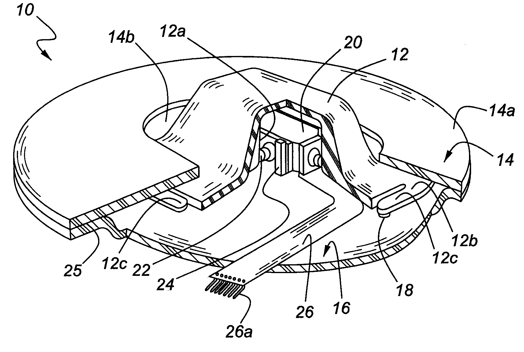
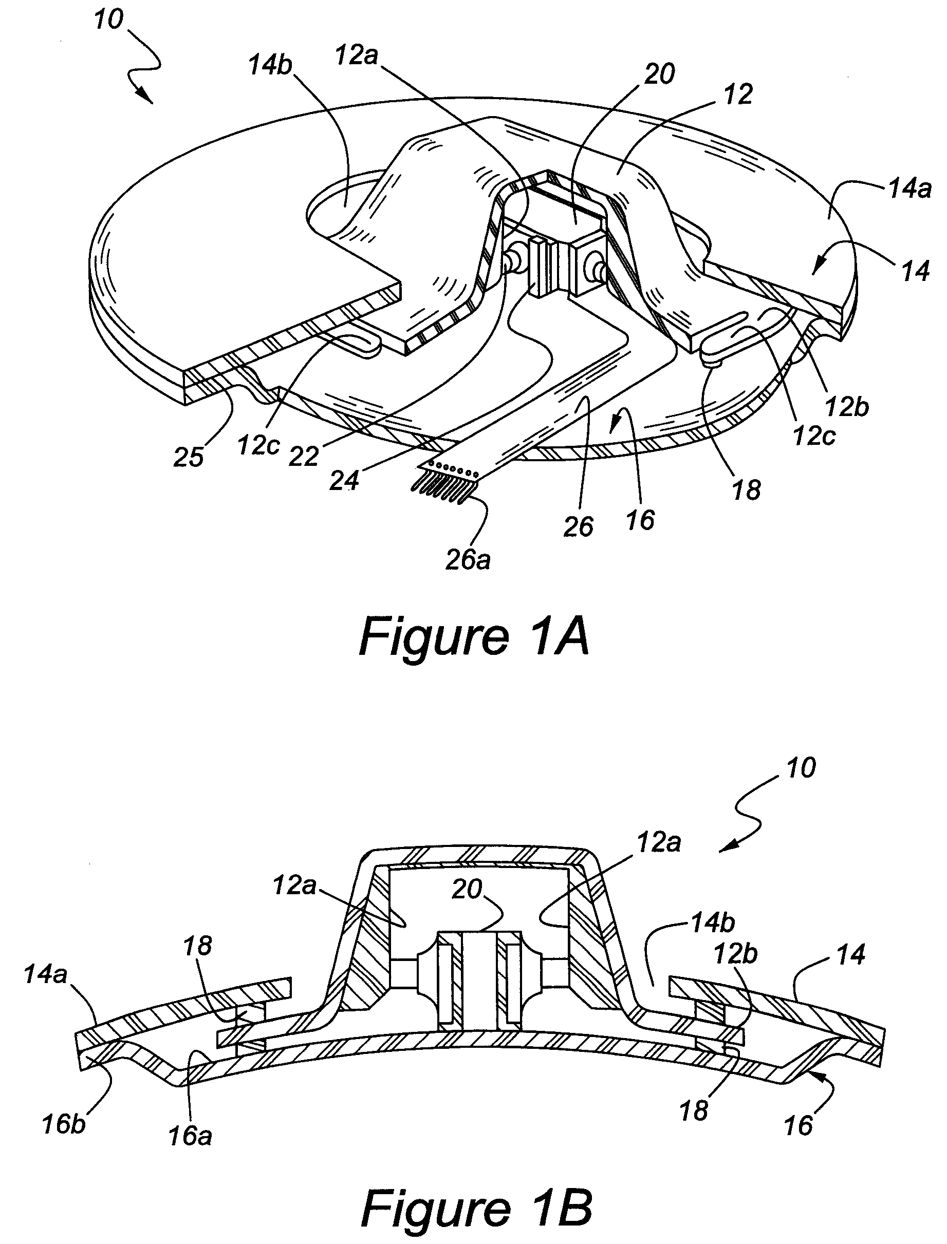
[0011]Referring to FIGS. 1A and 1B, a switch 10 is shown that includes a knob 12, a cover 14, and a base plate 16. Switch 10 may have a minimal thickness as compared to conventional switches. For example, knob 12 may have a width (e.g., the distance from cover 14 to base plate 16) of about eight millimeters. In one embodiment, knob 12 is configured to rotate about base plate 16. Alternatively, knob 12 may be ...


PUM


Abstract

Switches include electrical conductors for the transmission of switch signals. In some embodiments the conductor may include a flexible printed circuit. Alternatively, the conductor may be formed of a molded-interconnect device (MID), wherein portions of the switch include at least one electrical line/track.

Description

TECHNICAL FIELD[0001]The embodiments described herein relate to an electrical switch.BACKGROUND[0002]Conventional electrical switches may include a membrane that is positioned directly on a circuit board such as a printed circuit board (PCB). Portions of the membrane may be designed to close a circuit on the circuit board when engaged (e.g., touched or pressed) by a user. Closing of the circuit allows the flow of current through the switch thereby causing some operation (e.g., energization of an electric motor, processing by a controller and the like) to occur. Although conventional switches are useful, there exists a wide horizon for improvement. Particularly, the conventional switches are typically bulky as a result of a rigid circuit board. Moreover, in some cases, the bulky packaging of conventional switches imposes constraints on electrical switch styling.[0003]The embodiments described herein were conceived in view of these and other disadvantages of convention electrical swit...

Claims


Application Information

Patent Timeline
Patent Type & Authority Patents(United States)
IPC IPC(8): H01H25/04
CPCH01H25/04G05G9/047G05G2009/04744H01H2221/01H01H2221/012H01H2221/044
Inventor GARCIA-BRIZ, ALBERTO
Owner LEAR CORP
Why Eureka
Try Eureka