Power supply unit

A technology for a power supply device and a power conversion device, which is applied to circuit devices, battery circuit devices, current collectors, etc., can solve problems such as increasing the boost rate and reducing the operating voltage of solar cells, and achieve the effect of preventing the reduction of device conversion efficiency.

Inactive Publication Date: 2003-10-01
SANYO ELECTRIC CO LTD
View PDF0 Cites 108 Cited by
  • Summary
  • Abstract
  • Description
  • Claims
  • Application Information

AI Technical Summary

Problems solved by technology

[0007] On the other hand, the output voltage-output current characteristics of the solar cell are due to the Image 6 As indicated by the curve shown, if the step-up rate of the boost circuit increases and the current flowing increases, the operating voltage of the solar cell will move to the direction of decrease ( Image 6 left direction), thereby reducing the operating voltage of the solar cell

Method used


Image

  • Power supply unit
  • Power supply unit
  • Power supply unit

Examples


Embodiment Construction

[0023] Hereinafter, embodiments of the power supply unit in the present invention will be described in detail with reference to the drawings.

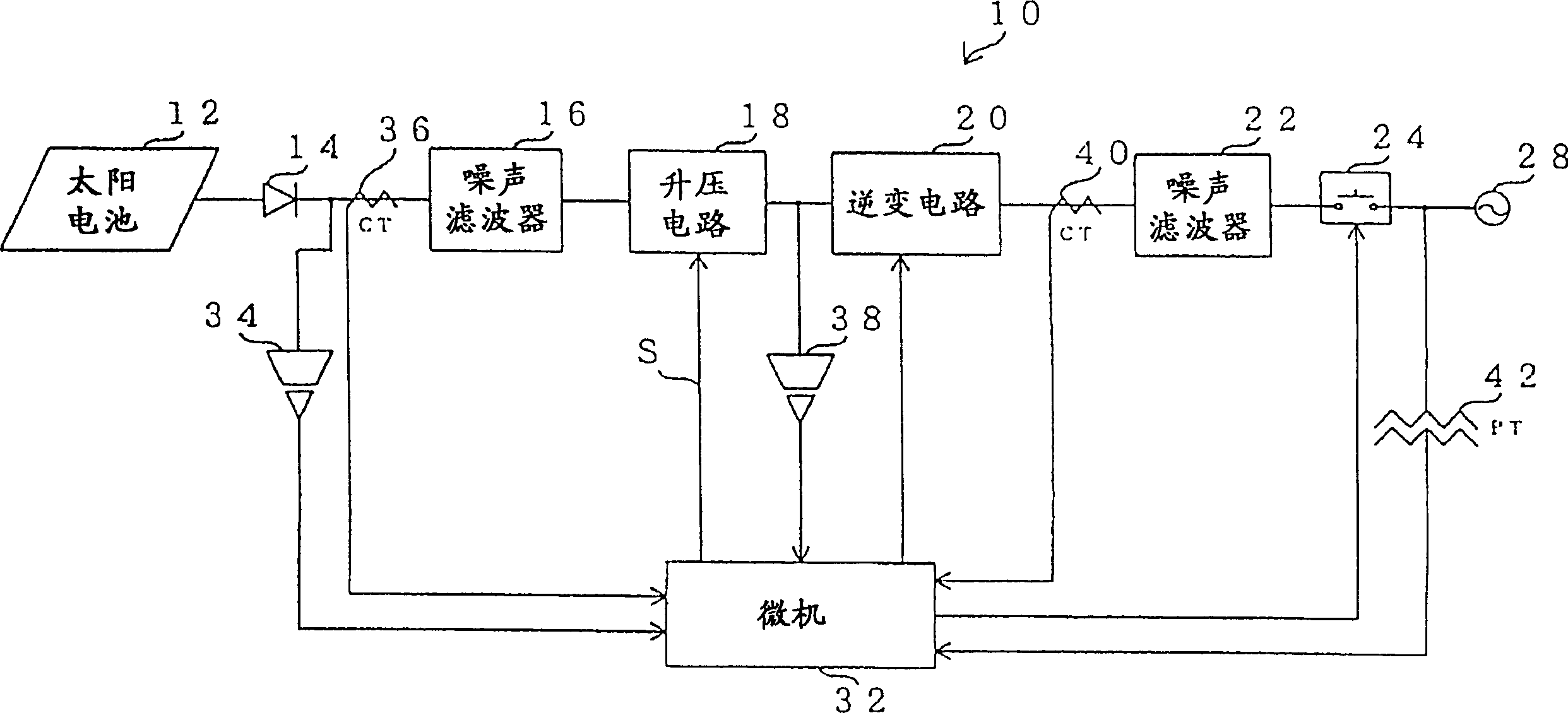
[0024] figure 1 It is a block diagram showing the configuration when the power supply device of the present invention is applied to a grid connection system connected to a commercial power grid. As shown in the figure, the solar power generation device 10 of this embodiment has a solar cell 12, and the output terminal of the solar cell 12 is connected to a noise filter 16 for direct current through a diode 14 for preventing backflow.

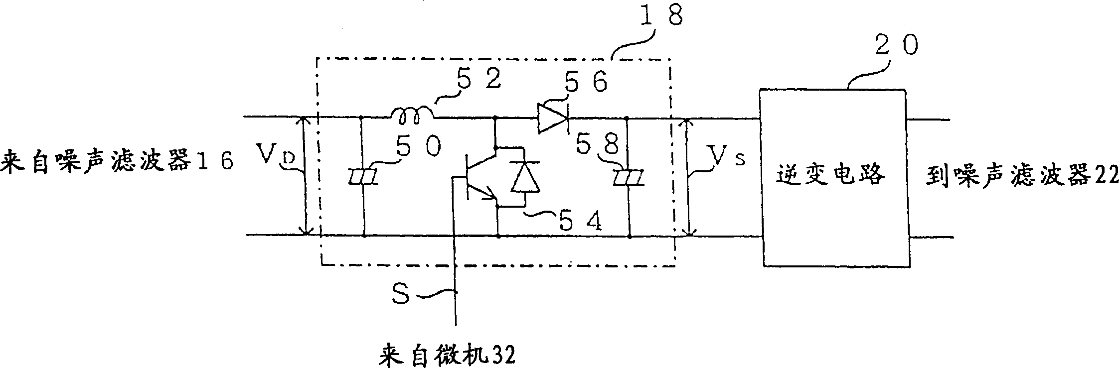
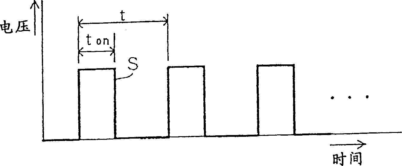
[0025] In addition, the output terminal of the noise filter 16 is connected to a booster circuit 18 that boosts the input DC power based on a switching signal S input from a microcomputer (hereinafter referred to as a microcomputer) 32 described later. The output terminal of 18 is connected to an inverter circuit 20 that converts the input DC power into AC power and outputs it, and the output terminal ...


PUM


Abstract

The invention results in a power supply unit that can always operate optimally. Start to input a switch signal to a boost circuit whose duty ratio boost rate can be changed according to the duty ratio of the input switch signal (step 100), and output current I from an inverter circuit connected to the rear stage of the boost circuit I Calculate the output power P of the inverter circuit I (Step 102) Afterwards, according to the output power P I Find the target voltage V after boosting the boost circuit M (step 104), at the actual output voltage V of the booster circuit S less than the target voltage V M increase the duty cycle of the switching signal, and decrease the duty cycle of the switching signal when the voltage is greater than the target voltage (step 106-step 112).

Description

technical field [0001] The present invention relates to a power supply device, in particular to a solar power generation device which converts DC power generated by a solar cell into AC power using an inverter circuit after boosting the voltage. Background technique [0002] In recent years, grid connection systems that use inverter circuits to convert DC power output from solar cells into AC power equivalent to commercial power are connected to commercial power grids to supply power to loads such as home appliances. attention. [0003] In an existing solar power generation device suitable for such a grid connection system, the voltage of the DC power output from the solar battery is boosted by a booster circuit such as a booster chopper circuit, and then the voltage of the DC power output by the solar battery is boosted by an inverter circuit. A device that converts boosted DC power into AC power. At this time, in the above-mentioned conventional solar power generator, th...

Claims


Application Information

Patent Timeline
Patent Type & Authority Patents(China)
IPC IPC(8): H02J7/35G05F1/67H02M7/48
CPCG05F1/67Y02E10/56H02J3/381H02S40/32H02J2300/26
Inventor 万里小路正树鬼塚圭吾时崎久森田功
Owner SANYO ELECTRIC CO LTD
Why Eureka
Try Eureka