
Method and system for imaging a patient

a patient and imaging technology, applied in the field of medical imaging systems, can solve the problems of patients lying still, limited total time of acquiring emission data,

Active Publication Date: 2009-04-14
GENERAL ELECTRIC CO
View PDF16 Cites 13 Cited by
  • Summary
  • Abstract
  • Description
  • Claims
  • Application Information

AI Technical Summary

Benefits of technology

"The patent describes a method and system for imaging a patient using a plurality of detectors and a patient table. The system detects annihilation photons and uses time-of-flight information to generate an image of the patient. The technical effect is improved accuracy and resolution in medical imaging."

Problems solved by technology

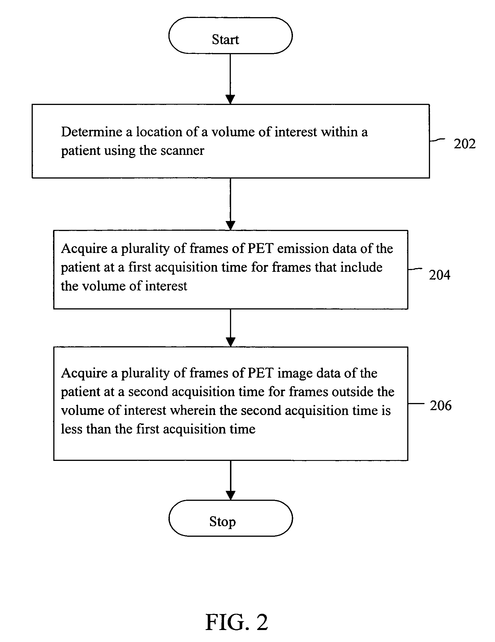
However, the total time of acquiring the emission data is limited by the decay of radioactive isotope and by the inability of the patients to lie still for extended durations.

Method used


Image

  • Method and system for imaging a patient
  • Method and system for imaging a patient
  • Method and system for imaging a patient

Examples


Embodiment Construction

[0011]Various embodiments of the invention provide a method and system for imaging a patient using a medical imaging system. The medical imaging system may be, for example, a Positron Emission Tomography (PET) scanner, and / or a PET / Computed Tomography (CT) dual modality scanner.

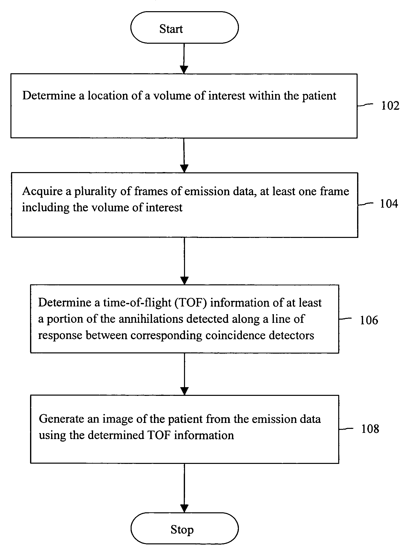
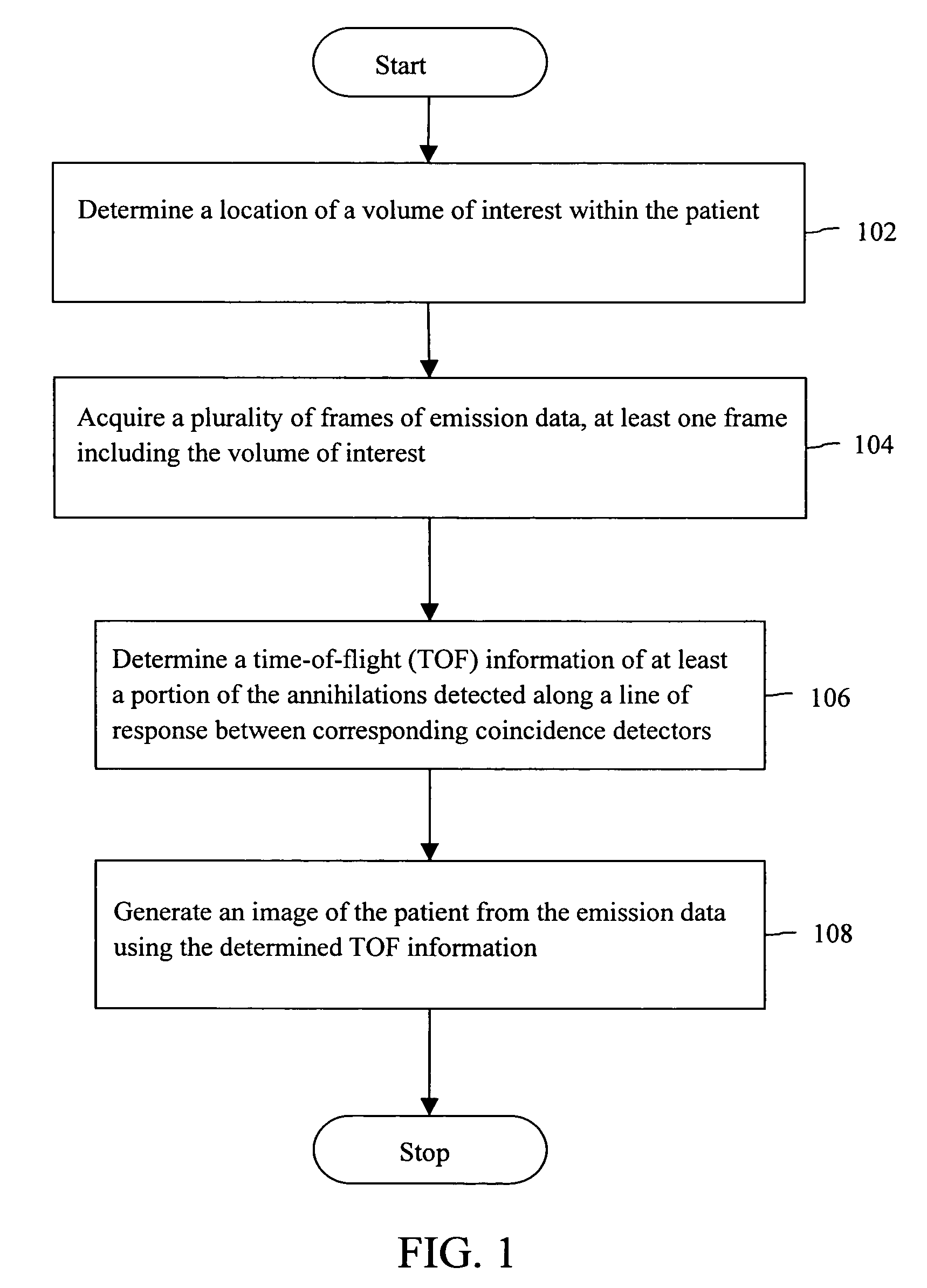
[0012]FIG. 1 is a flowchart illustrating a method for imaging a patient in accordance with an exemplary embodiment of the invention. At 102, a location of volume of interest within the patient is determined. In various embodiments of the invention, the volume of interest may be a particular region of the body of the patient, for example, an organ, a lesion, a nodule, a body part, etc. The volume of interest may be identified for imaging the particular region of the body of the patient for longer durations. The volume of interest may further be identified for selectively storing annihilation events.

[0013]In various embodiments of the invention, a volume of interest is determined, by localizing the volume of i...


PUM


Abstract

Methods and systems for imaging a patient are provided. The method includes determining a location of a volume of interest within the patient and acquiring a plurality of frames of emission data, at least one frame including the volume of interest. The method further includes determining a time-of-flight (TOF) information of at least a portion of the annihilations detected along a line of response between corresponding coincidence detectors and generating an image of the patient from the emission data using the determined TOF information.

Description

BACKGROUND OF THE INVENTION[0001]The invention relates generally to medical imaging systems, and more particularly, to Positron Emission Tomography (PET) scanners.[0002]PET scanners typically generate images depicting the distribution of positron-emitting nuclides in patients. The positron interacts with an electron in the body of the patient by annihilation, and then the electron-positron pair is converted into two photons. The photons are emitted in opposite directions along a line of response. The annihilation photons are detected by detectors that are placed on both sides of the line of response on the detector ring. The image is then generated based on the acquired emission data that includes the annihilation photon detection information.[0003]In PET scanners the image quality depends on the image statistics. The image statistics may be improved by acquiring the emission data for longer durations. However, the total time of acquiring the emission data is limited by the decay of...

Claims


Application Information

Patent Timeline
Patent Type & Authority Patents(United States)
IPC IPC(8): G01T1/164G01T1/166
CPCG01T1/1611A61B6/037G01T1/2985G01T1/1615
Inventor GANIN, ALEXANDERJANSEN, FLORIBERTUS PHILIPPUS MARTINUS HEUKENSFELDTAVILA, RICARDO SCOTTTROTTER, DINKO EDUARDO GONZALEZMANJESHWAR, RAVINDRA MOHANMILLER, JAMES VRADENBURGSEBASTIAN, THOMAS BABY
Owner GENERAL ELECTRIC CO
Learn More