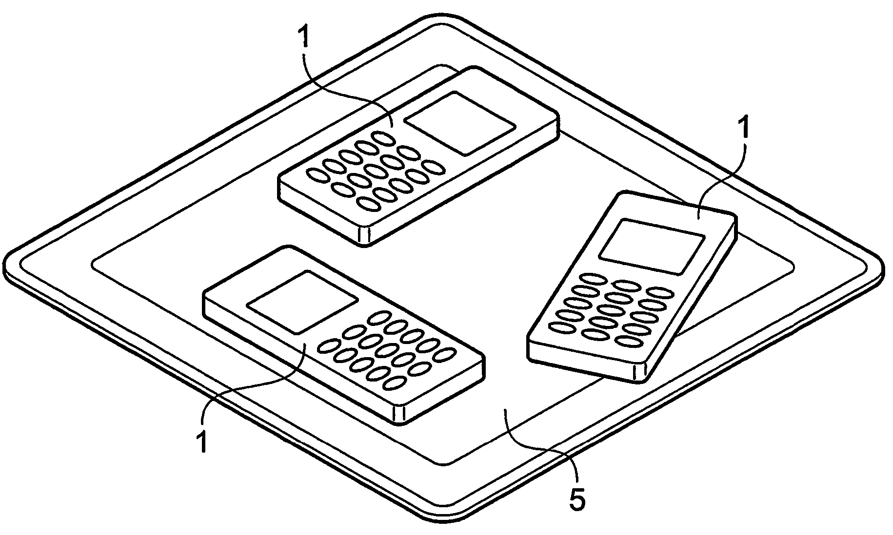
Retention of inductively rechargeable devices on an inductive charger

a technology of inductive charging and inductive charging, which is applied in the direction of marine propulsion, special-purpose vessels, vessel construction, etc., can solve the problems of inconvenient user requirements, disadvantages for users, lack of positive mechanical retention of such a surface, etc., and achieve the effect of convenient user information

Active Publication Date: 2009-04-14
PHILIPS IP VENTURES BV
View PDF14 Cites 49 Cited by
  • Summary
  • Abstract
  • Description
  • Claims
  • Application Information

AI Technical Summary

Benefits of technology

[0038]Alternatively, the connecting means of the charging unit may be identical to the connecting means of the device. This embodiment will be capable of attaching to itself and may be used on all devices and charging units. An example is a reusable tacky adhesive such as the glue used in Post-It® notes. A potential advantage of this is in the case where a device is capable of performing the function of a charging unit to another device.
[0039]In a yet further embodiment, there may be several different classes of pairs of types of connecting means, with each pair class attaching only to the other of the pair. A pot

Problems solved by technology

However in some situations, the lack of positive mechanical retention of such a surface may be a disadvantage for users.
But

Method used


Image

  • Retention of inductively rechargeable devices on an inductive charger
  • Retention of inductively rechargeable devices on an inductive charger
  • Retention of inductively rechargeable devices on an inductive charger

Examples


Embodiment Construction

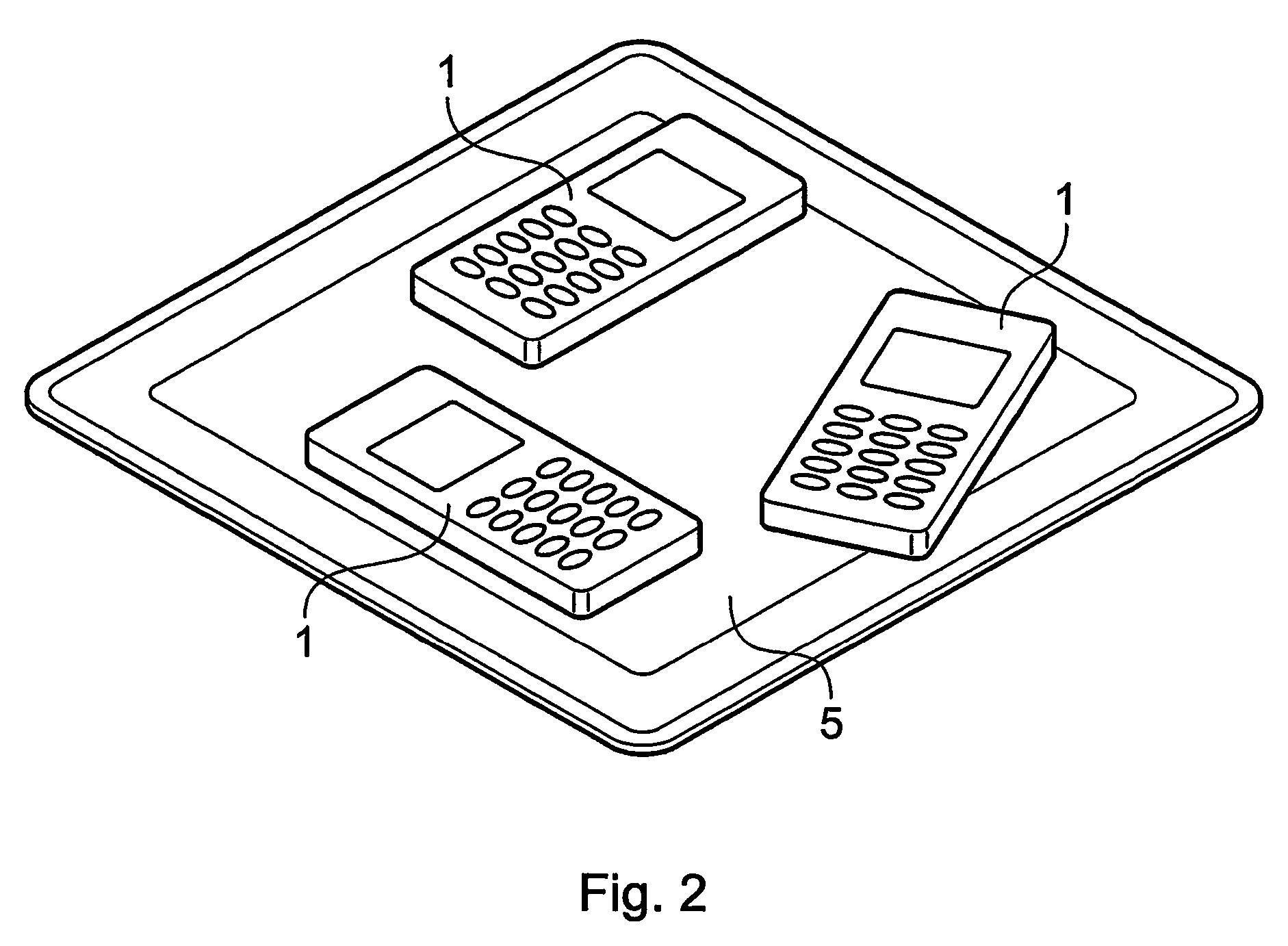
[0059]Referring to FIG. 3, there is shown a power receiving device 1, in this embodiment the device is a mobile phone. The mobile phone 1 has a connecting means 3 attached to the back of the phone. In this embodiment the connecting means 3 of the device 1 is a patch of self-adhesive Velcro® of the “male” type. This is black and slightly prickly, informing the user that the phone may be charged on a charging surface. FIG. 3 also shows a charging unit 5. In this embodiment the charging unit 5 is an inductive recharging pad. On the surface 7 of the pad 5 is attached a patch of self-adhesive Velcro® of the “female” type 9, which acts as the connecting means of the charging unit. This is black and slightly fuzzy, informing the user that the pad may charge devices.

[0060]To mate the phone 1 and the pad 5 temporarily, the user simply presses the phone 1 onto the pad 5 (or drops it, if the pad is below the phone) and the Velcro®3, 9 holds the phone in place on the pad. The phone can be place...


PUM


Abstract

There is disclosed a system and method for retaining portable rechargeable devices to recharging stations wherein one or other or both of the recharging station and the portable device are provided with connecting means adapted for temporary releasable connection of the two. This is particularly advantageous when used with recharging stations, which permit the device to be recharged in multiple places on the recharging station, providing a positive means of retaining the device. This is particularly advantageous if the recharging station is to be used in a mobile environment such as a car, or on a wall or ceiling.

Description

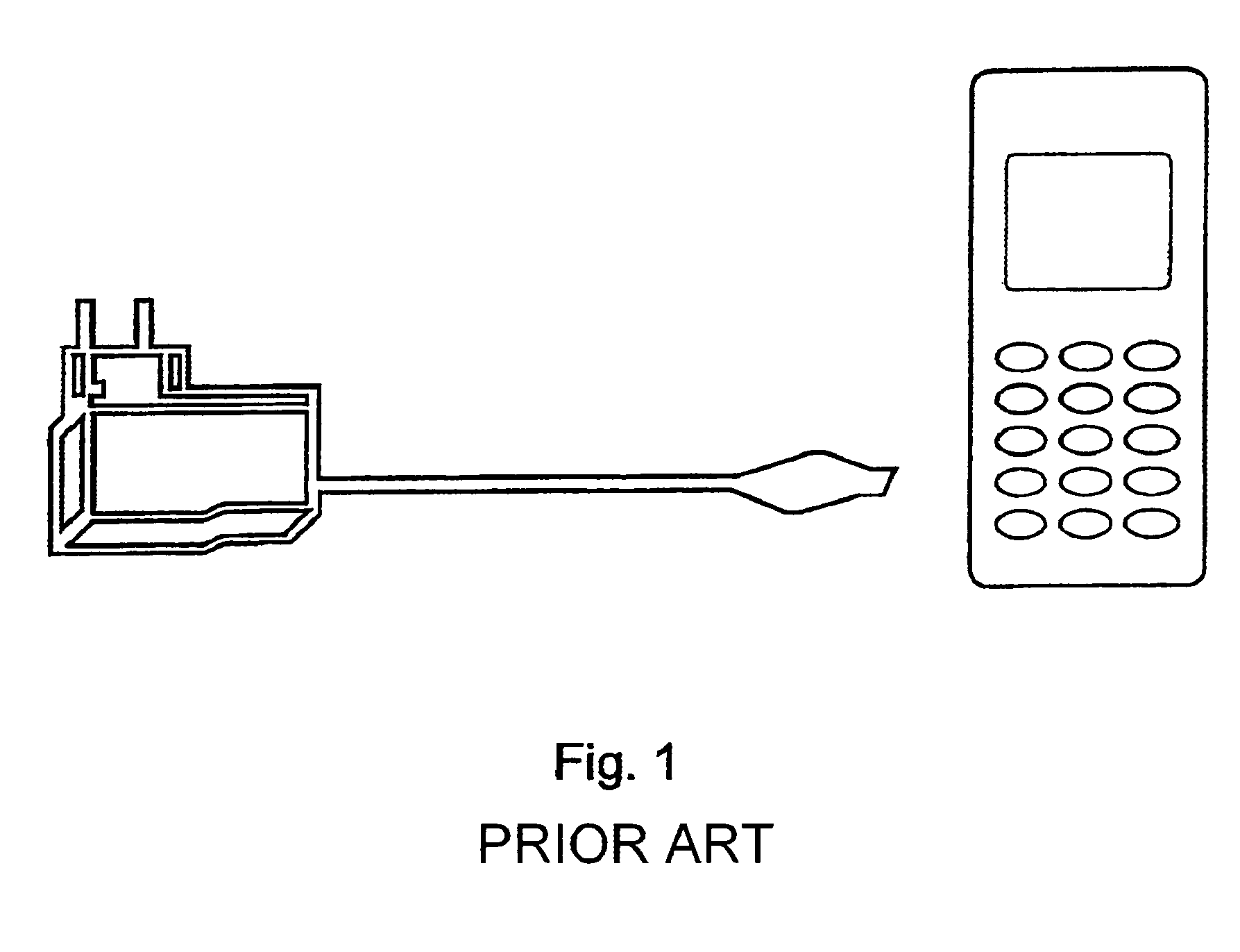
FIELD OF THE INVENTION[0001]This invention relates to a new system for temporary attachment of portable rechargeable devices to recharging stations, and a method of temporarily attaching portable rechargeable devices to their charging units.BACKGROUND OF THE INVENTION[0002]Today's portable rechargeable devices are typically recharged by temporarily connecting them to a recharger via a mating plug-in or clip-on connection. An example is the typical “floating wire” connection between a mains charger and a mobile phone (see FIG. 1).[0003]The connection serves two purposes:[0004]1) It electrically connects the device to its recharger, allowing transfer of power.[0005]2) It mechanically connects the device to its recharger, in a way which retains it securely against forces from accidental knocks and the like, but is easily removable by the user. This mechanical connection thus allows recharging to continue reliably until the user physically breaks the connection, and in some cases may al...

Claims


Application Information

Patent Timeline
IPC IPC(8): H02J7/00H02J5/00H02J7/02
CPCH02J5/005H02J7/025H02J7/0027H02J7/0044H02J7/0013H02J50/40H02J50/10H02J50/005H02J7/00716
Inventor BEART, PILGRIM GILES WILLIAMCHENG, LILY KA-LAI
Owner PHILIPS IP VENTURES BV
Why Eureka
Try Eureka