System, method, mobile terminal and computer software for providing electric energy to users

a technology for mobile users and mobile terminals, applied in the direction of electric variable regulation, sustainable buildings, instruments, etc., can solve the problems of inflexible, complex and inflexible solutions, and none of the known solutions provides an interface to the control server

Active Publication Date: 2017-05-11
EPSPOT
View PDF2 Cites 0 Cited by
  • Summary
  • Abstract
  • Description
  • Claims
  • Application Information

AI Technical Summary

Benefits of technology

[0009]The object of the present invention is therefore to mitigate the above problems, and thus enable delivery of electric energy at distributed locations in a manner being uncomplicated and straight-forward both for the providers and the consumers.
[0011]This system is advantageous because it enables electricity consumers to share electric energy from standard outlets based on communication via standard communication terminals, such as mobile telephones. The proposed system also provides simple and reliable interfaces both between the supply nodes and the server node; and between the server node and the mobile terminals. Consequently, new supply nodes can be added to the system simply by setting up a connection to the server node, for example over the Internet. Authorized consumers may likewise communicate with the server node over the Internet, and thus remote control the electric outlets of the supply nodes.
[0012]According to one preferred embodiment of this aspect of the invention, the activation request includes an identity string uniquely identifying the specified outlet. The identity string is adapted to be included in the activation request in connection with generating the activation request. To this aim, the first supply node contains data representing the identity string in the form of: alphanumerical information adapted to be read by a user and fed manually into the mobile terminal, an optical code adapted to be automatically read into the mobile terminal via a scanner means, and / or an amount of data configured to be transferred to the mobile terminal via a short-range radio interface, e.g. in accordance with the NFC standard (NFC=Near Field Communication). Thereby, a user may conveniently inform the server node of outlet he / she wishes to activate.
[0017]According to a further preferred embodiment of this aspect of the invention, the inquiry from the supply node to the server node also contains the activation request. In response to the inquiry, the server node is configured to establish communication with the user terminal via the short-range radio interface. Thereby, it is not necessary for the user terminal to set up a separate connection to the server node (e.g. over the Internet), which, in turn, enables consumption of electric energy at locations where users cannot communicate via conventional land-based communication systems, for instance onboard ships at sea.

Problems solved by technology

Of course, this is a severe limitation, especially for electric-vehicle drivers who may want to travel a relatively long distance from a point A (say at his / her home) to a point B, where re-fuelling (or rather re-charging of batteries) may be required before continuing.
However, these solutions are relatively complex and inflexible, particularly in terms of rendering the distribution system available for new customers in a convenient manner.
Moreover, none of the known solutions provides an interface to the control server, which enables new suppliers to be added by simple means.

Method used


Image

  • System, method, mobile terminal and computer software for providing electric energy to users
  • System, method, mobile terminal and computer software for providing electric energy to users
  • System, method, mobile terminal and computer software for providing electric energy to users

Examples


first embodiment

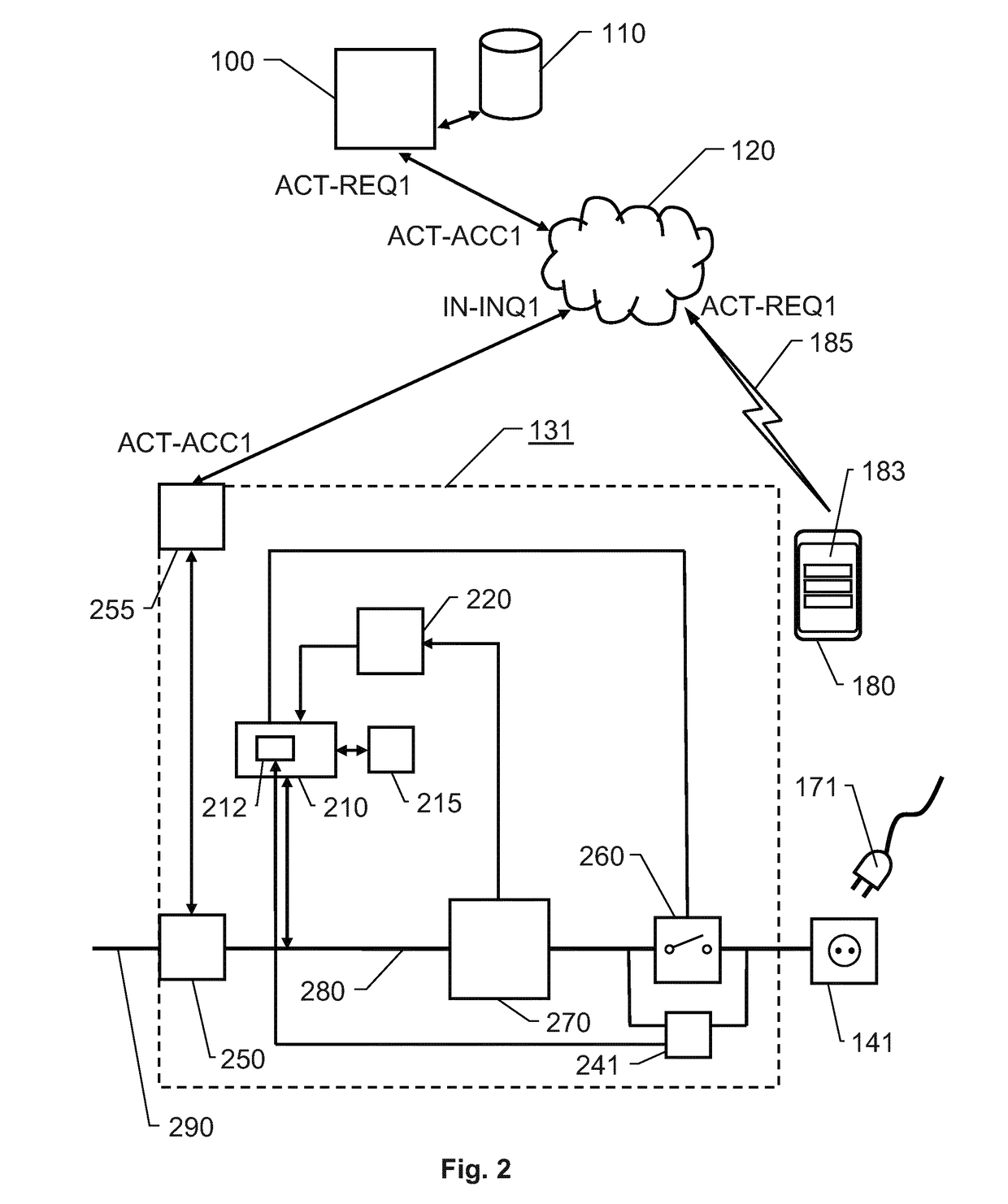
[0042]FIG. 2 illustrates further details of a supply node 131 according to the invention.

[0043]As mentioned above, each supply node 131, 132 and 13n is configured to receive electric energy from an external power source. In FIG. 2, this is symbolized by an input power line 290. The input power line 290, in turn, is typically represented by a power grid. However, the input electric power may equally well originate from a standalone source of energy, e.g. a set of solar panels or a generator. In any case, the supply node 131 is configured to provide output electric energy based on the input energy from the external power source 290 via at least one remote-controlled outlet 141 associated with the node 131.

[0044]To enable communication between the supply node 131 and the server node 100 (e.g. in respect of the activation accept ACT-ACC1), the supply node 131 preferably includes a network interface 255 configured to be connected to the at least one communication network 120. In the embo...

second embodiment

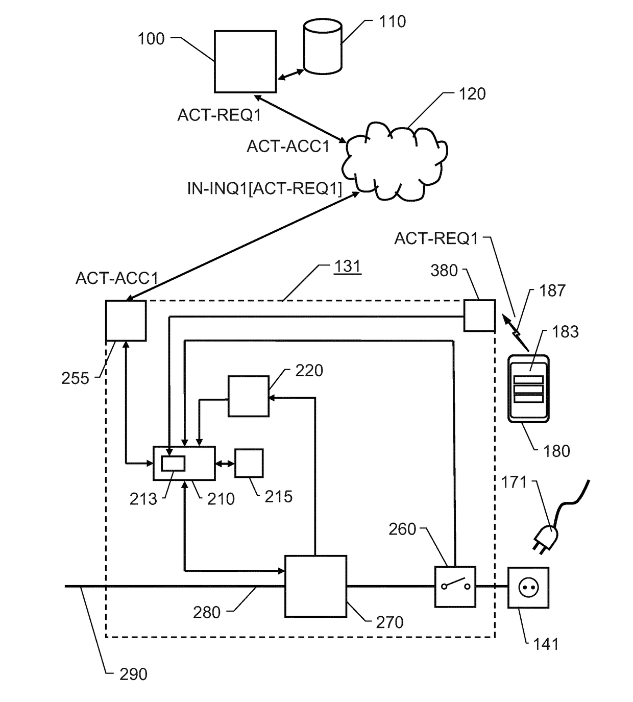
[0050]FIG. 3 illustrates details of a supply node 131 according to the invention. Here, all elements, units and messages bearing the same reference labels as described above with reference to FIG. 2 designate the same elements, units and messages as in FIG. 2. For illustrating purposes, in the embodiment shown in FIG. 3, the supply node 131 does not include any powerline-to-Ethernet converter. Therefore, instead, the processing unit 210 is arranged to communicate internally in the supply node 131 exclusively via dedicated data lines.

[0051]Moreover, in FIG. 3, the supply node 131 includes a short-range radio interface 380 (e.g. of NFC type) configured to detect the presence of a mobile terminal 180 in proximity to the outlet 141 via electromagnetic-field fluctuations 187. A second trigger module 213 in the supply node 131 is configured to generate an inquiry IN-INQ1[ACT-REQ1] in response to a mobile terminal 180 being detected by the short-range radio interface 380. Analogous to the ...


PUM


Abstract

A system for providing electric energy to users includes a server node, a set of supply nodes and a set of mobile terminals. One or more communication networks connect the server node to the supply nodes. Each supply node provides output energy via a remote-controlled outlet. Each mobile terminal communicates with the server node over a wireless interface. The supply nodes repeatedly send respective instruction inquiries to the server node, which also receives activation requests from the mobile terminals specifying a particular outlet and an identity of a mobile-terminal user. In response to an activation request, the server node checks if the user identity is authorized to activate the outlet, and if so; in response to an instruction inquiry from a first supply node associated with the outlet, sends an activation accept to the first supply node enabling output of electric energy from the outlet.

Description

CROSS-REFERENCE TO RELATED APPLICATION(S)[0001]This application is a national stage application (filed under 35 § U.S.C. 371) of PCT / EP14 / 063377, filed Jun. 25, 2014 of the same title; the contents of which are hereby incorporated by reference.BACKGROUND OF THE INVENTION[0002]The present invention relates generally to provision of electric energy to mobile users for sharing on commercial grounds.[0003]Today, an increasing number of apparatuses and devices are powered by electricity. This, per se, creates a strong demand for reliable and efficient supply of electric power. Further, for most consumers, electric power is exclusively available at one single place, namely at the consumer's home, or the address associated with his / her electricity contract. Of course, this is a severe limitation, especially for electric-vehicle drivers who may want to travel a relatively long distance from a point A (say at his / her home) to a point B, where re-fuelling (or rather re-charging of batteries) ...

Claims


Application Information

Patent Timeline
Patent Type & Authority Applications(United States)
IPC IPC(8): G05F1/66G06Q50/06H02J13/00
CPCG05F1/66G06Q50/06H02J13/0017H02J13/00022Y04S40/126Y02E60/00Y02B90/20H02J7/00H02J13/00
Inventor OLIN, JAN CHRISTIAN
Owner EPSPOT
Why Eureka
Try Eureka