Method and a device for optically detecting the position of an object by measuring light reflected by that object

a technology of optical detection and light reflection, which is applied in the direction of electronic switching, pulse technique, instruments, etc., can solve the problems of difficult adaptation of devices designed for surfaces of different sizes to surfaces of different sizes, high cost of keypads, and inability to easily adapt devices designed for surfaces of given sizes. achieve the effect of improving the detection of objects, avoiding the number of emitters, and more reliable detection

Inactive Publication Date: 2009-04-14
H2I TECH
View PDF13 Cites 38 Cited by
  • Summary
  • Abstract
  • Description
  • Claims
  • Application Information

AI Technical Summary

Benefits of technology

[0025]This method provides much more reliable detection than when analyzing only the signal received by the transducer delivering the maximum energy, in particular when the object to be detected is not aligned with a transducer.
[0047]The wavelength of the emitted light may be in one of the following ranges of wavelengths: UV, visible, infrared, the emitters and receivers used then being less complex and less costly than emitters / receivers of coherent (laser) light or electromagnetic emitters / receivers.

Problems solved by technology

The patent FR 2 443 173 describes a keypad with movable keys including a plurality of light emitters and a plurality of light receivers for detecting depression of the keys; that keypad is costly because it requires a large number of mechanical and optoelectronic components and it is complex because light emitters and receivers are distributed throughout the area in which the keys are situated.
One drawback of the above devices is that it is necessary to distribute the optical components over substantially the whole of the perimeter of the input area with sufficient geometrical accuracy not to falsify calculations based on data representative of signals delivered by the light receivers to determine the position in the input area of the object (finger, etc.) used to indicate data selected by the user.
As a result of this, such devices remain relatively costly.
Furthermore, a device designed for a surface of given size is not easily adaptable to a surface of different size.
That method has a first drawback in that it is not able to detect the position of an object accurately if it is not perfectly aligned with the infrared receiver.
It has a second drawback in that it is not able to obtain the precise position of an object of irregular shape (for example a finger) even if the said object is aligned with a detector, in particular because the signal received after reflection from an irregular shape is far from linear.
Naturally, one solution to that problem is to increase the number of transducers, to the detriment of the cost and the complexity of the device.
One drawback of that method is that it requires a large number of samples to train the neural network.
If the neural network is trained with a relatively small number of samples (relative to the number of neurons), the result of the interpolation effected by the neural network is reliable only for detecting objects under the same conditions as apply to the above-mentioned samples, and it becomes difficult to predict and very uncertain as soon as the measurement conditions depart from the training conditions.
Over and above this, the execution of a neural network in an embedded system consumes a detrimental quantity of computation resources.

Method used


Image

  • Method and a device for optically detecting the position of an object by measuring light reflected by that object
  • Method and a device for optically detecting the position of an object by measuring light reflected by that object
  • Method and a device for optically detecting the position of an object by measuring light reflected by that object

Examples


Embodiment Construction

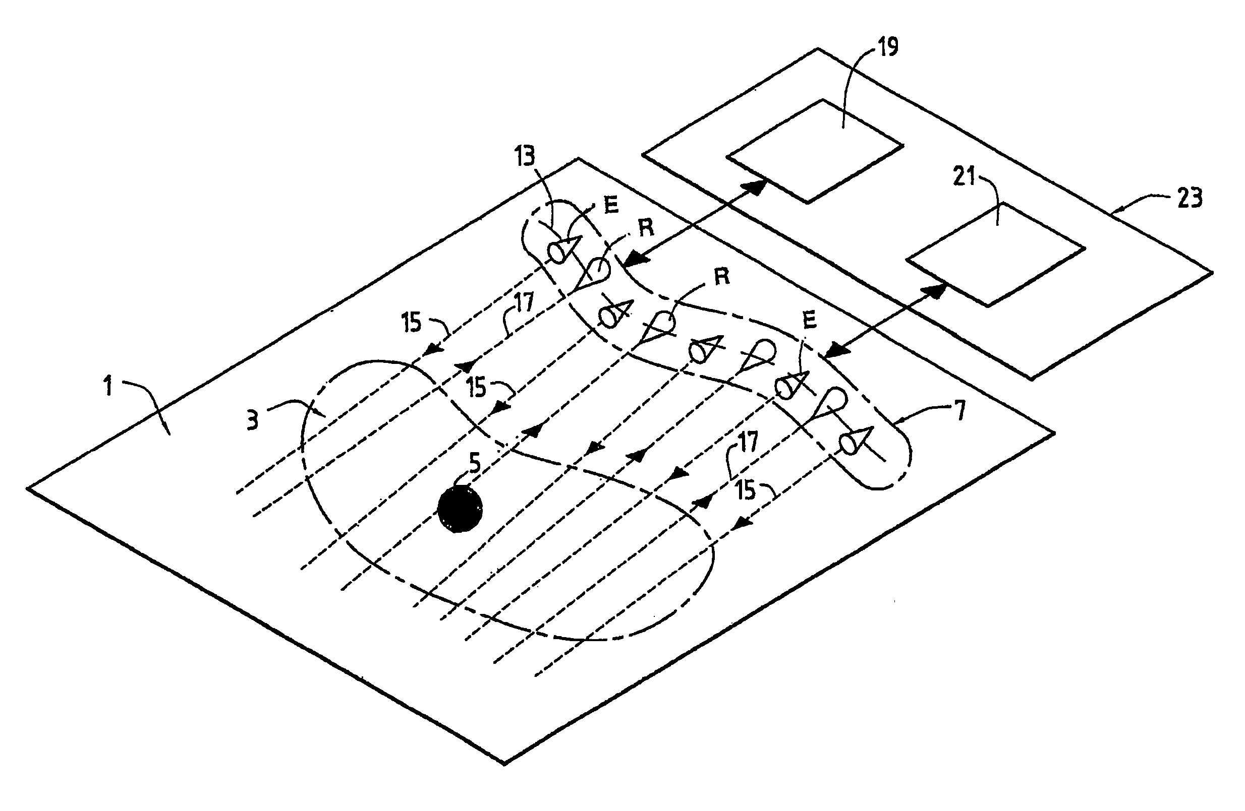
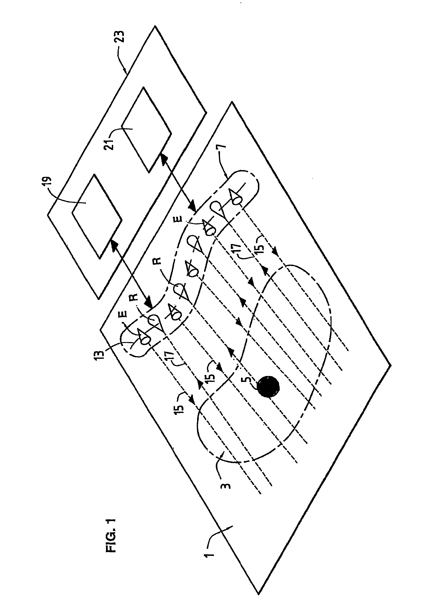
[0069]FIG. 1 shows a surface 1 including a particular area 3 on which an object 5 is to be detected in accordance with the invention.

[0070]The invention applies in particular to determining the position of an object 5 such as a finger of a user or a writing instrument or a pointer such as a stylus that is placed near or in contact with the particular area 3.

[0071]Thus this particular area 3, which corresponds to a detection area, may be of any shape and size.

[0072]Moreover, an alternating set 7 of emitters E and receivers R of light is disposed in the vicinity of the particular area 3, all on the same side of the object 5, the emitters E emitting light that covers the whole of the area 3.

[0073]In the present embodiment, the surface 1 is substantially plane.

[0074]However, this is optional, provided that the light emitted by the emitters E is not intercepted by the surface 1 in the detection area 3.

[0075]In the FIG. 1 example, the emitters E and receivers R are disposed in a single li...


PUM


Abstract

This detection method comprises: a step during which a receiver measures the quantity of light reflected by an object when the object is illuminated by an emitter for at least two different emitter—receiver pairs on the same side relative to the object, a step of calculating at least two characteristic values from the measured values, and a step of determining at least one position of the object by directly reading a table indexed by the two characteristic values, the content of said table being predetermined and set before said measurement step.

Description

[0001]The invention relates to a method and to a device for determining the position of an object on a particular area of a surface, in particular, although not exclusively, for the purposes of inputting data.[0002]One technical field of the invention is that of fabricating keypads and similar devices for manual data input to computers, fixed or mobile telephones, personal digital assistants, or any other electronic device.BACKGROUND OF THE INVENTION[0003]Many optical systems are used to detect the position of a member or an object for the purposes of inputting data, in particular alphanumeric data.[0004]The patent FR 2 443 173 describes a keypad with movable keys including a plurality of light emitters and a plurality of light receivers for detecting depression of the keys; that keypad is costly because it requires a large number of mechanical and optoelectronic components and it is complex because light emitters and receivers are distributed throughout the area in which the keys a...

Claims


Application Information

Patent Timeline
Patent Type & Authority Patents(United States)
IPC IPC(8): G01B11/14G01B11/03G06F3/041G06F3/042H03K17/94
CPCG06F3/0421
Inventor CAVALLUCCI, GILLESSYLVESTRE, JULIEN P.PLANTIER, PHILIPPE G.
Owner H2I TECH
Why Eureka
Try Eureka