Front end interface for data receiver

a data receiver and front end technology, applied in the field of data receivers, can solve the problems of poor data recovery, receivers cannot properly decode signals, and receivers cannot efficiently amplify signals

Inactive Publication Date: 2009-04-14
IBM CORP
View PDF8 Cites 22 Cited by
  • Summary
  • Abstract
  • Description
  • Claims
  • Application Information

AI Technical Summary

Problems solved by technology

However, when the common mode level of the signal arriving at the receiver lies outside of the voltage range that the receiver is designed to handle, the receiver cannot amplify the signal efficiently.
Poor data recovery then results.
In other words, the receiver cannot properly decode a signal in which a long consecutive string of “1s” or “0s” appears at the input to the receiver.
Moreover, in systems in which only the data signal is transmitted but not the clock, it is difficult to recover the clock from the transmitted signal when the transmitted signal has long strings of either “1”s or “0”s.
Heretofore, such flexibility has not been available in SerDes communication systems.
However, some drawbacks of the front end interface circuit shown in FIG. 4 are that it does not perform DC offset cancellation, nor test for cable faults, nor provide for up-channel communication, such as is needed to transmit equalization information back to the transmitter for use in adjusting coefficients of a feed-forward equalizer at the transmitter.

Method used


Image

  • Front end interface for data receiver
  • Front end interface for data receiver
  • Front end interface for data receiver

Examples


Embodiment Construction

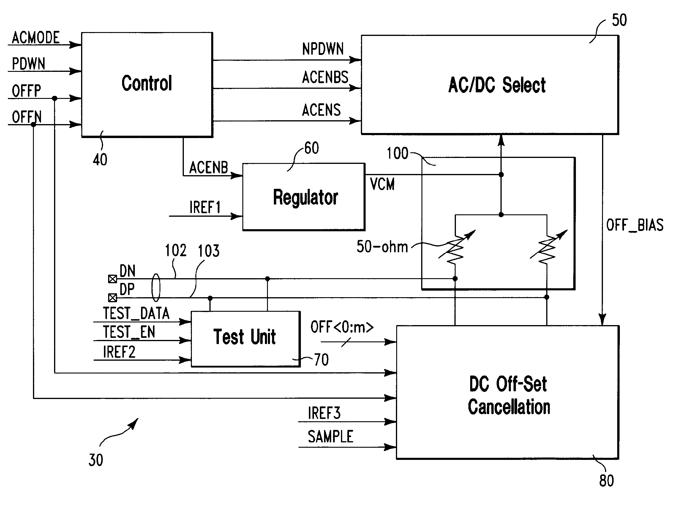
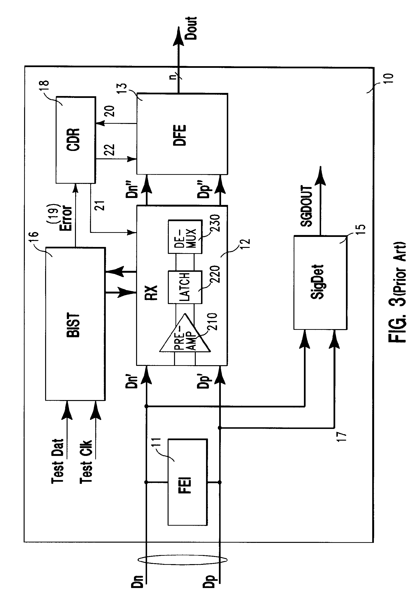
[0029]With reference to FIG. 5, a front end interface unit 30 according to one embodiment of the invention includes six functionally defined units: an adjustable termination network unit 100, a control unit 40, an AC / DC mode selection unit 50, a regulator 60, a test unit 70, and a DC offset cancellation unit 80. The front end interface unit is designed for use in a receiver complex 10 such as that shown and described above with respect to FIG. 3. The front-end interface (FEI) unit 30 has AC and DC operational modes for operation according to both an AC coupled transmission scheme and a DC coupled transmission scheme, respectively.

[0030]Termination network 100 provides coarse and fine control over adjustable values of impedances used to terminate the differential signal lines 102 and 103 on which the data signals Dn and Dp arrive at the receiver complex 30. Through a set of binary vectors input to the termination network 100, the values of the terminating impedances are controlled ac...


PUM


Abstract

A data receiver is provided which includes a front end interface circuit having an alternating current (AC) transmission receiving mode and a direct current (DC) transmission receiving mode. The front end interface circuit includes an offset compensation circuit operable to compensate a DC voltage offset between a pair of differential signals input to the data receiver. The front end interface circuit further includes an AC / DC selection unit operable to switch between (a) the DC transmission receiving mode, and (b) the AC transmission receiving mode, such that the data receiver is operable in (i) the DC transmission mode in which the offset compensation circuit is disabled, (ii) the DC transmission mode in which the offset compensation circuit is enabled, (iii) the AC transmission mode in which the offset compensation circuit is disabled, and (iv) the AC transmission receiving mode in which the offset compensation circuit is enabled.

Description

BACKGROUND OF THE INVENTION[0001]The present invention relates to data receivers, especially for high-speed wired communications.[0002]High-speed serial data transmission is conventionally performed according to either a direct current (DC) coupled scheme or an alternating current (AC) coupled scheme, as shown in FIGS. 1 and 2, respectively. In a DC coupled scheme, as shown in FIG. 1, the transmitter is conductively connected to the receiver at DC as well as AC via a DC conducting medium, e.g., through one or more cards, cables, connectors, packages, and backplanes, etc. By contrast, as shown in FIG. 2, in an AC coupled scheme, AC coupling capacitors 7 are placed in the path of signals between the transmitter and remote receiver to allow only AC signals to pass, while blocking the flow of current at DC between the transmitter and receiver. For this reason, the AC coupling capacitor is also known as a DC blocking capacitor. DC blocking capacitors can be provided on the same integrate...

Claims


Application Information

Patent Timeline
Patent Type & Authority Patents(United States)
IPC IPC(8): H04L25/34
CPCH04L25/0274H04L25/0296
Inventor HSU, LOUIS L.CORDREY-GALE, MATT R.MASON, JAMES S.MURFET, PHILIP J.SELANDER, KARL D.SORNA, MICHAEL A.XU, HUIHAO
Owner IBM CORP
Why Eureka
Try Eureka