Roller grill assembly for cooking human food

a technology for grilling and human food, which is applied in the direction of roasting apparatus, manufacturing tools, food shaping, etc., can solve the problems of dislocating or disengaging the drive chain from the drive, and affecting the cooking effect of the food. , to achieve the effect of preventing the disconnection of the drive chain

Inactive Publication Date: 2009-04-21
STAR MFG INT
View PDF26 Cites 16 Cited by
  • Summary
  • Abstract
  • Description
  • Claims
  • Application Information

AI Technical Summary

Benefits of technology

[0010]The present invention improves over the prior art and provides a number of advantages for heating and cooking human food, and for protecting the food from contaminants. The present invention provides a drive system for rotating tubular rollers used for heating and cooking foods. The invention provided a means for driving the roller tubes to rotate relative to the housing which include a drive member mounted to the housing and driven by a power source such as a motor. The roller tubes are provided with driving engagement structure such as a sprocket or a gear. The roller tubes are aligned in a group so that there is a roller tube at each end of the group. The invention further provides an idler member that includes a sprocket, gear, or the like, mounted with the housing as by a stud. Drive linkage such as a drive chain is drivingly connected with the drive member, with the roller tube drive engagement structure, and with the idler member. The connection is such that the direction of movement of the drive linkage is that the drive member pulls the linkage so that the linkage moves from the engagement with the roller tubes toward and about the idler member, and thence from the idler member to the drive member. In other words, the drive member is pulling the linkage in the direction from the idler member toward the drive member without any tubular heating members located in between. This arrangement thus allows the pulling force that is transmitted by the linkage from the drive member to be directly transmitted to the idler member, rather than directly transmitted to the end of one of the roller tubes. The force applied by the linkage against the idler member is transferred to the housing. After the linkage passes from the idler member to the drive member, it extends about the drive member to move next to engagement with the engagement means of the roller tubes. Reinforcing structure, such as a strut with an opening to allow passage of the linkage, can also be used in mounting the idler member to the housing to better withstand the forces of the drive linkage exerted about it, and to resist distortion of the idler member and its mounting.
[0011]In another embodiment of the present invention, there is provided a roller grill assembly having a drive chain protection assembly for preventing a drive chain from being displaced or disengaged from a drive system for rotating tubular rollers used for heating and cooking foods. The roller grill assembly has roller tubes that are capable of rotating relative to a housing that include a drive member mounted to the housing and driven by a power source such as a motor. The roller tubes are provided with driving engagement structure such as a sprocket or a gear. The roller tubes are aligned in a group so that there is a roller tube at each end of the group. The invention further provides an idler member that includes a sprocket, gear, or the like, mounted with the housing as by a stud. Drive linkage such as a drive chain is drivingly connected with the drive member, with the roller tube drive engagement structure, and with the idler member. The drive chain protection assembly for preventing the drive chain from being displaced or disengaged from the drive system has a pair of idler members and a cam member adapted to engage a stop member.
[0017]The roller tubes can further be mounted so that their central axes are aligned to extend at an angle of about 3° to 5° relative to the housing. The central axis of the idler member of the drive assembly can also be aligned with the axes of the roller tubes as part of the alignment of from about 3° to 5°. The 3° to 5° alignment of the roller tubes allows for a convenient arrangement so that operator has a good view of the food items cooked upon the roller grill from the operator's primary work point. Additionally, the operator can serve food items from the opposite ends of the housing wherein the elevation of the rollers is higher. The 3° to 5° elevation is of a lesser incline than the 15° incline known in the prior art, so as to be less likely to encounter a problem of food items rolling down the 3° to 5° incline if they are inadvertently bumped or struck by a serving instrument.
[0018]The invention further features cover structure mounted to the frames of the housing about the ends of the roller tubes. One of these cover structures can act to cover the sprockets or other engagement means at the ends of the roller tubes as well as cover the linkage or chain of the drive assembly. The cover structures act to block heat loss from the ends of the roller tubes. The cover structure on each of the housing frames adjacent the roller tubes also provides a means for mounting the heating members that extend through the roller tubes. Openings can be provided through the structure to receive ends of the heating members to support same. The heating members can have a heating element with a wound spiral configuration. The spacing between each of the spiral winds is more compact at the ends of the element than in the center.

Problems solved by technology

However, the load exerted by the tube upon such bearings has caused deformation, and has caused wear and tear upon the bearing so that grease and other liquids have passed through the bearing seals to enter other parts of the housing such as the drive assembly of the housing.
However, there have been problems caused by the application of the drive chain force from the drive member directly to pulling a roller tube.
This has resulted in distorting the end of that roller tube, and also in distorting the bearing with which the roller tube is mounted to allow grease and liquids to pass by the bearing into enclosures such as into the area housing the drive components.
It has also been found that when cleaning roller tubes if force is exerted on one or more of the roller tubes it may displace or disengage the drive chain from the drive member or drive assembly.
There are also situations where exerting force to one or more of the roller tubes will result in the drive chain being jammed within the roller grill assembly that causes the roller heating tubes to malfunction or not to rotate.
Further, with roller tubes aligned at an angle of about 15° relative to the housing in the prior art, inconvenience has arisen in an operator trying to serve food from the grill when the operator is located at the end of the grill at the upper incline of the tubes.
Such controls have been exposed to view during operation, and also exposed to possible impingement or bumping by a person or by some object moved about the assembly, to change the setting of a control.
A problem with this type of unit has been that the operators using them have, at times, lifted the component up to have access to the food, but not returned the hinged member to a lower position to better cover the food.
A problem with these guards is that one could sneeze or cough into the openings into the passage to contaminate the food, or other contaminants could float through the openings to contact the food.
A problem with these types of guards is that the ledge at the bottom of the opening hinders accessibility to food and makes it more difficult to see the food.

Method used


Image

  • Roller grill assembly for cooking human food
  • Roller grill assembly for cooking human food
  • Roller grill assembly for cooking human food

Examples


Embodiment Construction

[0051]The following detailed description illustrates the invention by way of example and not by way of limitation. This description will clearly enable one skilled in the art to make and use the invention, and describes several embodiments, adaptations, variations, alternatives and uses of the invention, including what we presently believe is the best mode of carrying out the invention. As various changes could be made in the above constructions without departing from the scope of the invention, it is intended that all matter contained in the above description or shown in the accompanying drawings shall be interpreted as illustrative and not in a limiting sense.

Overall General Description

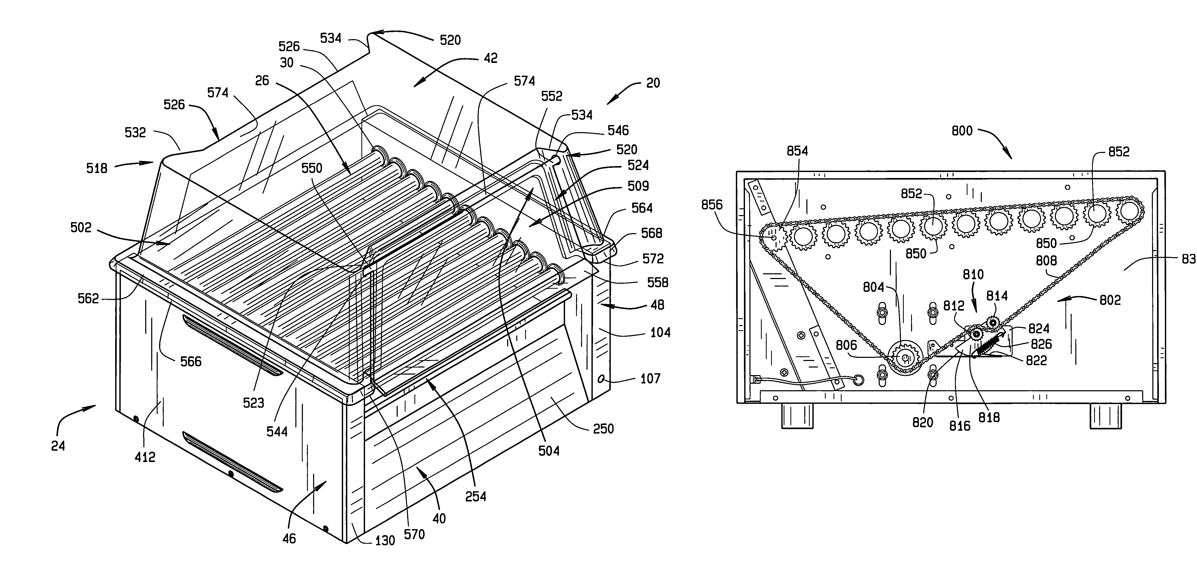
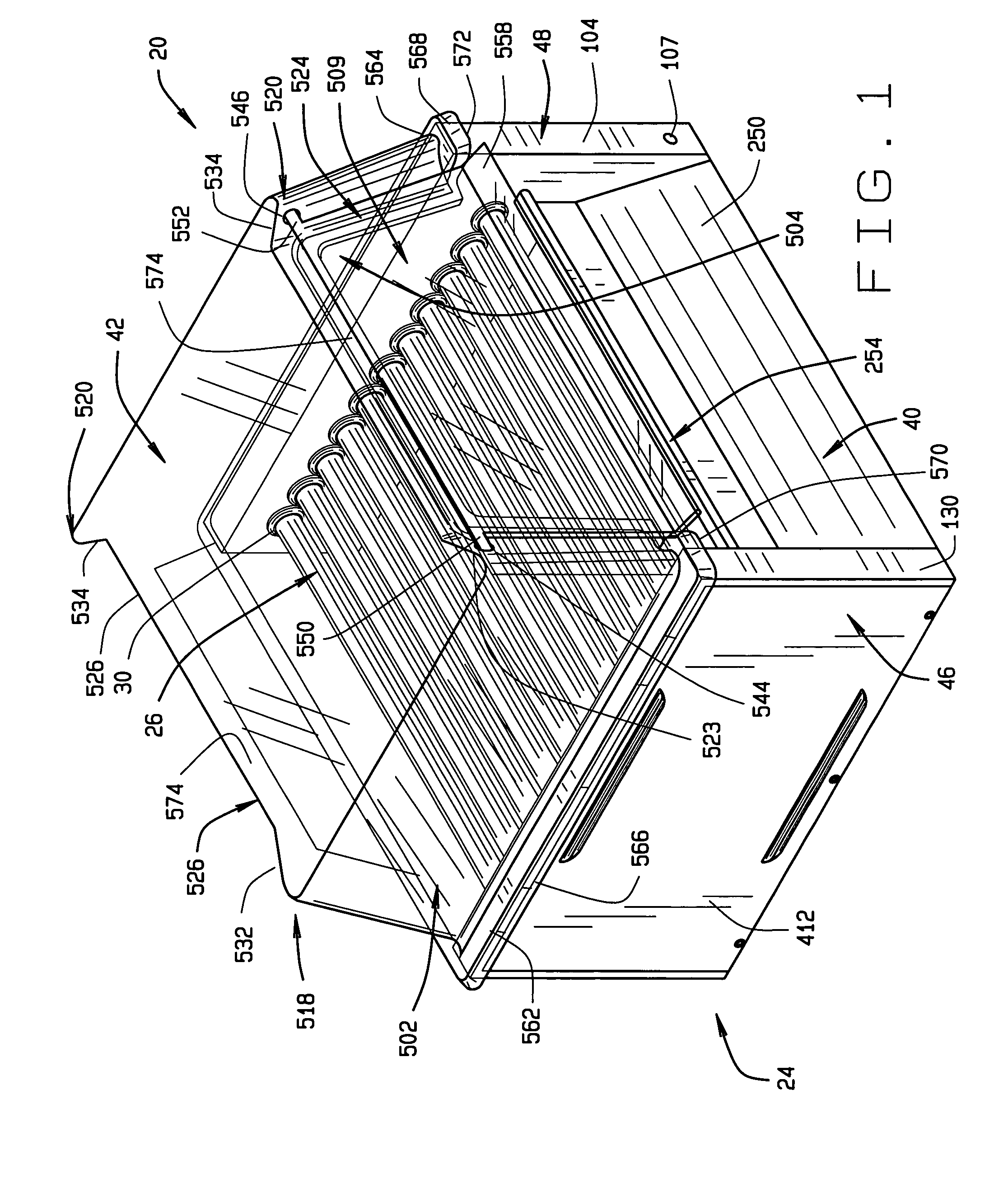
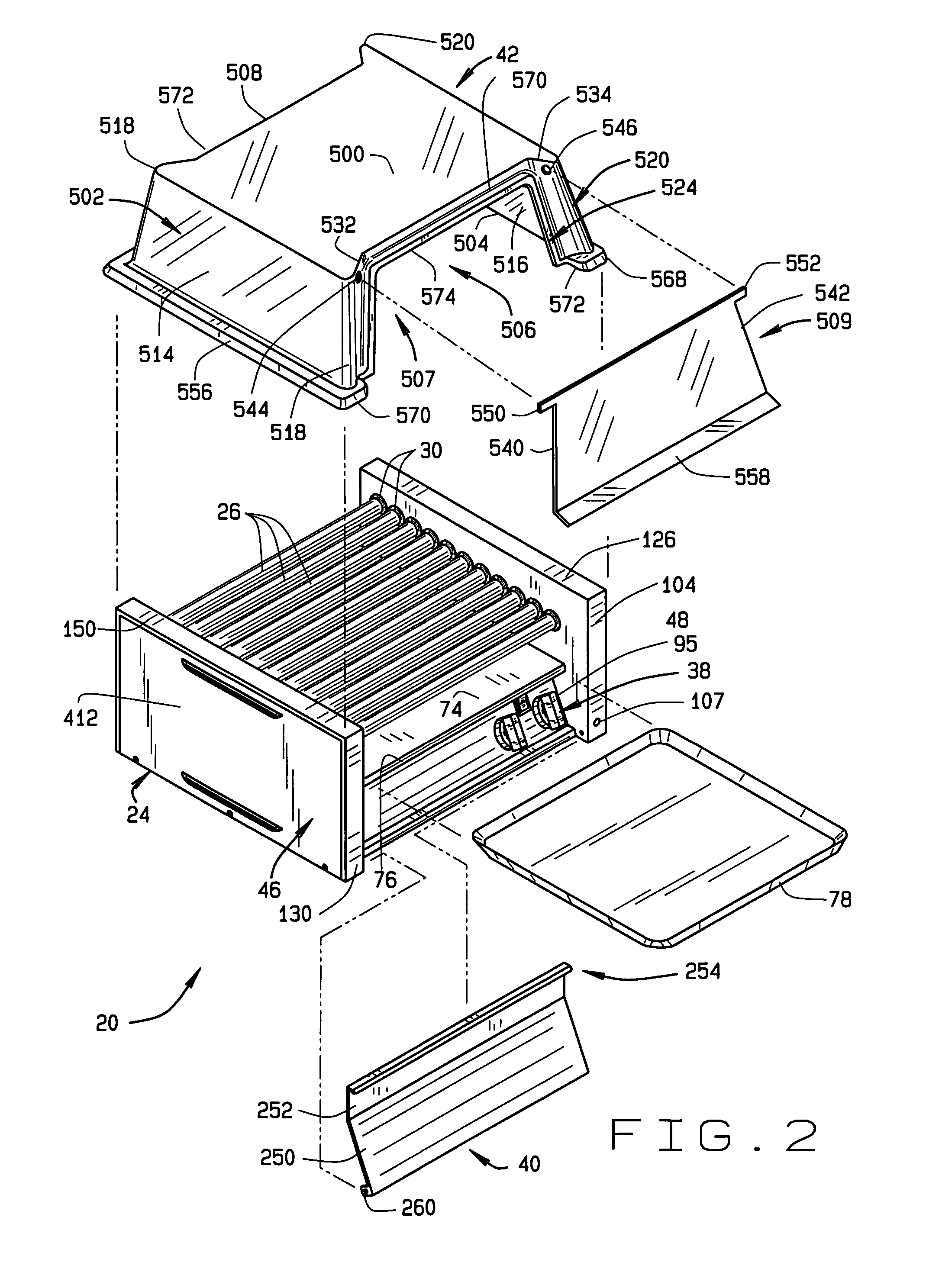
[0052]First, an overall general description will be given. With reference to FIGS. 1-15 of the drawings, the roller grill assembly for cooking human food is generally designated 20. The assembly 20 generally comprises a main housing 24, upon which are mounted a plurality of rotatable tubular cooking...


PUM


Abstract

A grill assembly for cooking human food is disclosed that comprises a housing having a support frame, a plurality of tubular cooking members rotatably mounted with said support frame, a drive assembly for driving the tubular cooking members to rotate relative to the frame comprising an electric motor having a drive shaft, a drive chain, a drive sprocket drivingly connected with the motor shaft, the tubular members having sprockets with teeth for engaging the drive chain, and a drive chain tensioned assembly.

Description

CROSS REFERENCE TO RELATED APPLICATIONS[0001]This application claims priority to U.S. Provisional Application 60 / 103,645 filed Oct.9, 1998. This application is also a continuation-in-part application of U.S. patent application Ser. No. 10 / 080,211 filed on Feb. 21, 2002, now U.S. Pat. No. 6.782,802 which was a continuation application of U.S. patent application Ser. No. 09 / 414,785 filed on Oct.8, 1999, now U.S. Pat. No. 6,393,971.STATEMENT REGARDING FEDERALLY SPONSORED RESEARCH OR DEVELOPMENT[0002]Not applicable.BACKGROUND OF THE INVENTION[0003]This invention relates to assemblies for cooking human food, and in particular to such assemblies that use heated tubes that are rotatably mounted to a housing so that food can be placed upon the roller tubes to be heated. The invention also relates to guard covers for human food cooking assemblies so that germs such as from sneezing, and contaminants in the ambient air, are blocked from impinging upon the food. The invention further relates t...

Claims


Application Information

Patent Timeline
Patent Type & Authority Patents(United States)
IPC IPC(8): A47J37/06A47J27/14A47J36/06A47J37/04B23P19/08
CPCA47J36/06A47J37/048B23P19/084
Inventor HUNOT, THOMASHUEGERICH, MICHAEL LEESEKO, JAMES J.
Owner STAR MFG INT
Why Eureka
Try Eureka