Triple layer industrial fabric for through-air drying process

Inactive Publication Date: 2006-09-21
ASTENJOHNSON
View PDF6 Cites 4 Cited by
  • Summary
  • Abstract
  • Description
  • Claims
  • Application Information

AI Technical Summary

Benefits of technology

[0021] The fabrics of the present invention are unique in that the warp yarns are vertically stacked and paired, and are interwoven with pairs of intrinsic weft binder yarns so as to provide a triple layer fabric structure. The combination of stacked warp yarns and pairs of intrinsic weft binder yarns allows the fabrics of this invention to be woven so as to provide a high projected open area while, at the same time, providing adequate dimensional stability, stretch resistance and seam strength.
[0023] Further, the weave pattern is selected to maximize the number of yarn knuckles on the PS surface of the PS layer, which is the surface to receive the resin coating. This serves to improve the attachment of resin coating to the fabric by providing a large number of surface features which can be encapsulated by the resin. DETAILED DESCRIPTION

Problems solved by technology

Firstly, a high amount of projected open area, being the amount of open space per unit area projected through a fabric when viewed perpendicularly to the plane of the fabric, is required.
If the carrier fabric is a closely woven structure, it will tend to become filled when the polymeric resin is applied, thus closing or unduly restricting the air passages.
If the fabric does not have this stability, it may become narrowed or lengthened along its centre line, or suffer from creasing, or undulations across its width, any of which may impair its runnability and effectiveness.
Such variations in the otherwise smooth planar nature of the fabric may cause localized variations in the paper product being conveyed by the fabric, which can lead to sheet breaks and a disruption in the operation of the papermaking machine.
If the crimp is insufficient for a given seam width, the warp yarns will tend to slide apart from the weft yarns, and the seam is more likely to fail.
Designers of carrier fabrics such as those of the prior art have been faced with the difficulty of meeting and reconciling these and other criteria.

Method used


Image

  • Triple layer industrial fabric for through-air drying process
  • Triple layer industrial fabric for through-air drying process
  • Triple layer industrial fabric for through-air drying process

Examples


first embodiment

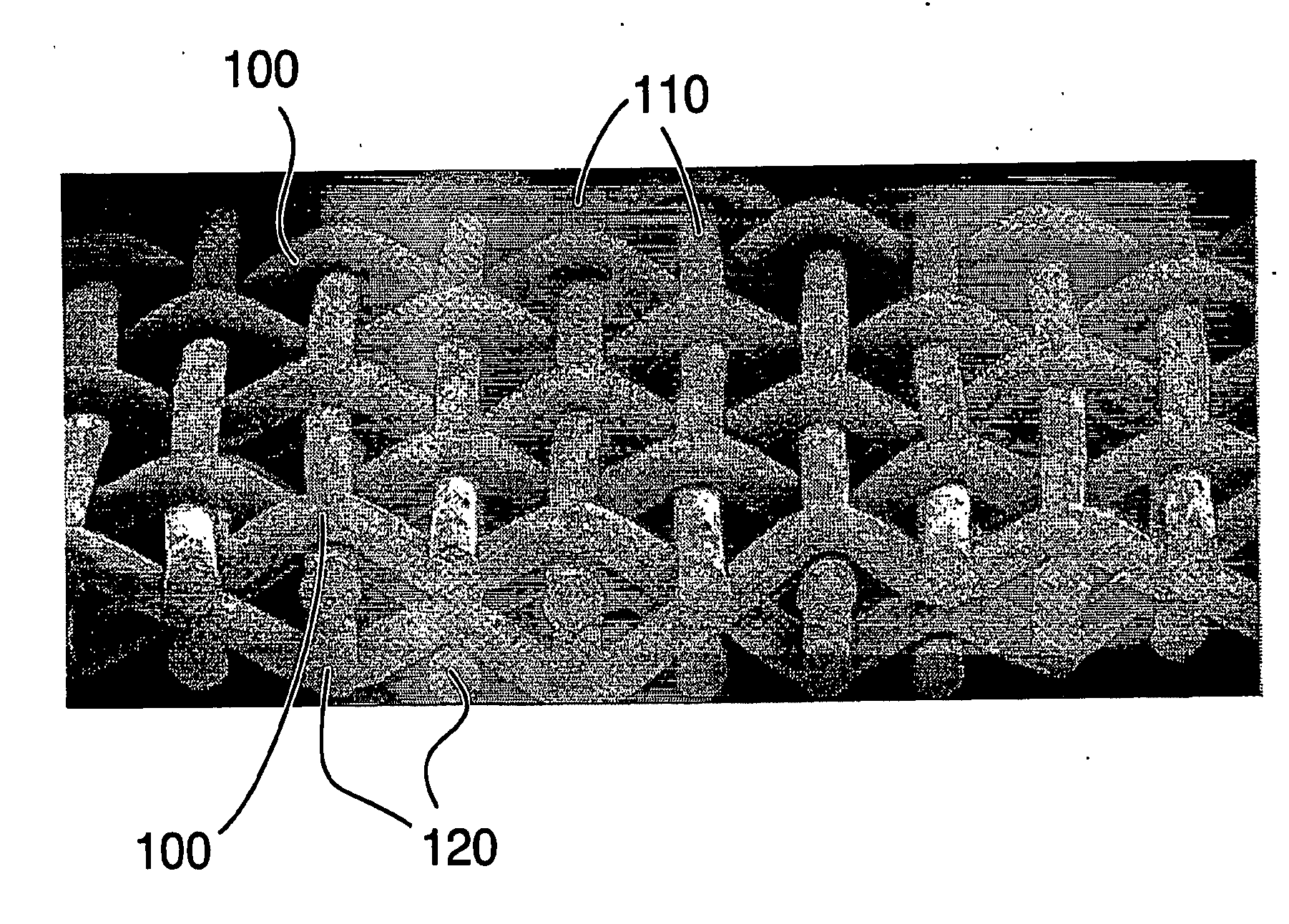
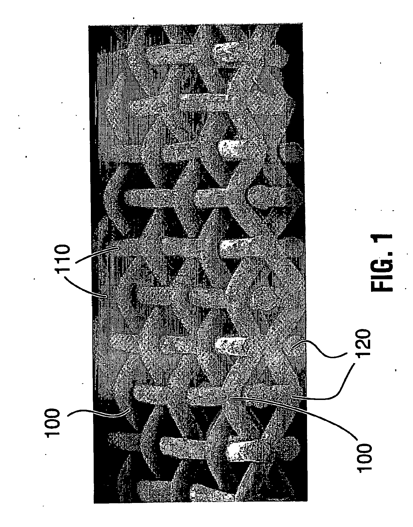
[0029]FIG. 1 is a photographic isometric view of the invention;

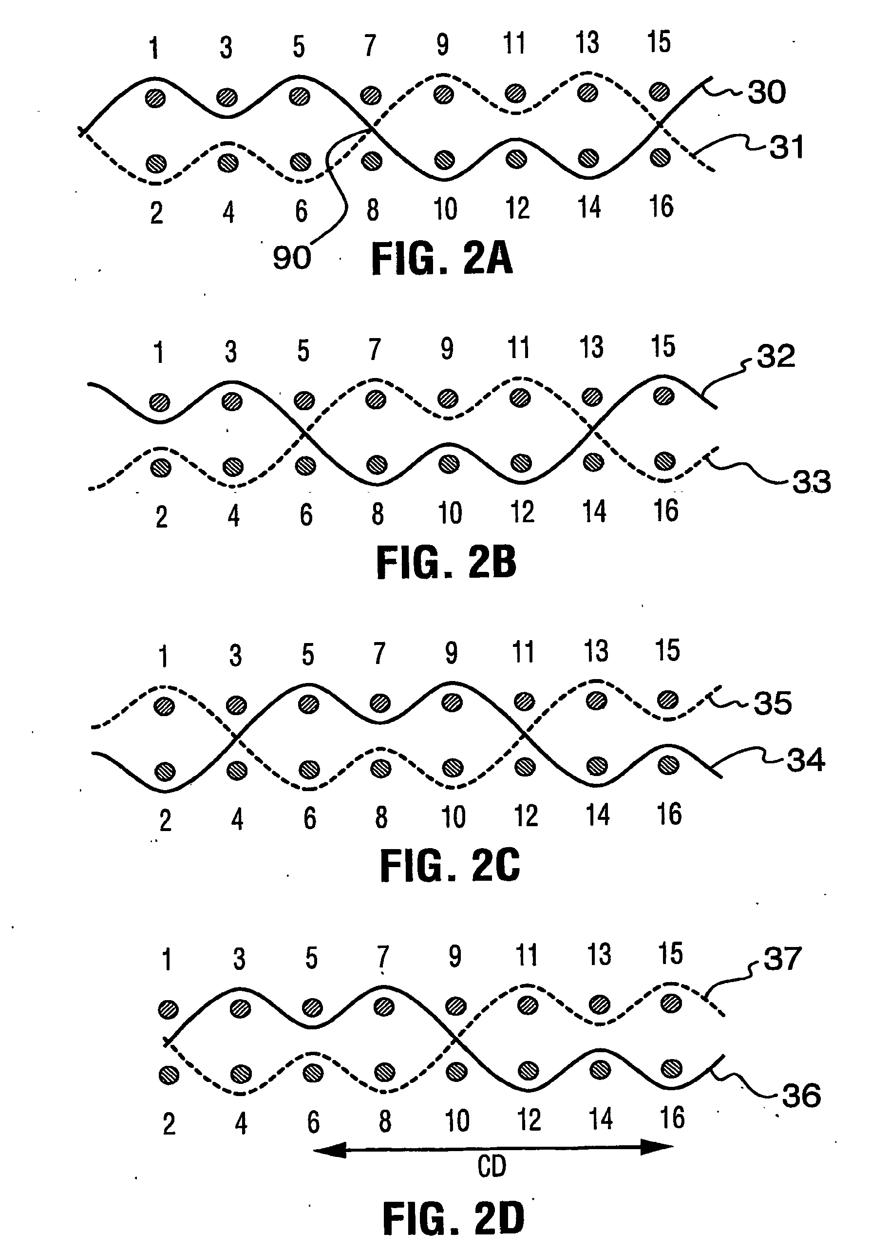
[0030]FIGS. 2A to 2D show the paths in the CD of four successive weft yarn pairs of the embodiment of FIG. 1;

[0031]FIG. 3 shows the path in the MD of one stacked pair of warp yarns of the embodiment of FIG. 1;

[0032]FIG. 4 is a weave diagram showing one repeat of the weave pattern of the embodiment of FIG. 1; and

fourth embodiment

[0033]FIGS. 5A to 5C show respectively the paths of one weft yarn pair of a second, third and fourth embodiment of the invention.

[0034] Referring to FIG. 1, it can be seen that the fabric of this embodiment is woven to a plain weave design in each of the PS layer 70 and the MS layer 80, to which each member of each pair of weft yarns, identified by the generic reference numeral 100, contributes. In each embodiment, the paths of each member of each pair of weft yarns 100 in each repeat comprise two portions, so that each member alternates between the PS layer 70 and the MS layer 80, and so that between the first and second portions of the repeat, the first and second members of the pair of weft yarns 100 exchange positions at an exchange point 90. In the first portion, the first member is exposed over a preselected number N1 of PS warp yarns identified by the generic reference numeral 110, while the second member is exposed over a preselected number N2 of MS warp yarns identified by ...


PUM

PropertyMeasurementUnit
Fractionaaaaaaaaaa
Fractionaaaaaaaaaa
Areaaaaaaaaaaa

Abstract

A triple layer woven industrial fabric, particularly suitable for through-air drying applications, has a paper side (PS) layer and a machine side (MS) layer of polymeric warp and weft yarns woven to a repeat pattern wherein all the warp yarns are arranged as vertically stacked pairs, all the weft yarns comprise pairs of intrinsic weft binder yarns, and each pair of weft yarns forms an unbroken weft path in both the PS layer and the MS layer whereby when either the first or second member of the pair passes from the PS layer to the MS layer, the other member of the pair passes from the MS layer to the PS layer at an exchange point located between at least one common pair of warp yarns.

Description

[0001] The present invention relates to industrial fabrics, more particularly to fabrics for use as through-air dryer fabrics to mold a web of cellulosic fibers into a three dimensional paper structure in a papermaking machine. BACKGROUND OF THE INVENTION [0002] In the manufacture of paper, an aqueous slurry of about 99% by weight of water and 1% by weight of cellulosic fibers and other papermaking constituents is deposited from a headbox onto a moving forming fabric, or in between two moving forming fabrics on a two-fabric papermaking machine. The web is initially formed and partially drained in the forming section, and is transported downstream where it is consolidated and dried by known means, such as conventional press dewatering in the press section, and evaporative drying in the dryer section. However, if the finished sheet is intended to have liquid absorbency properties, for end uses such as for tissue or towel, improved results can be obtained through the use of a through-a...

Claims


Application Information

Patent Timeline
IPC IPC(8): D03D11/00D21F1/00D21F7/12
CPCD21F1/0045Y10T442/2861Y10T442/3301Y10T442/3854Y10T442/3195Y10T442/3366Y10T442/3203Y10T442/178Y10T442/183Y10T442/3211Y10T442/2139Y10T442/3317Y10T442/172Y10T442/3179Y10T442/335
Inventor STONE, RICHARDJOHNSON, DALE B.
Owner ASTENJOHNSON
Why Eureka
Try Eureka