
High efficiency conical mills

a conical mill, high-efficiency technology, applied in the direction of grain treatment, etc., can solve the problems of increasing the cost of the product, generating substantial noise in the operation of the conical mill, inconsistent energy imparted to the solid product or powder, etc., to reduce heat generation, eliminate or eliminate the effect of nois

Active Publication Date: 2021-04-27
QUADRO ENG CORP
View PDF20 Cites 1 Cited by
  • Summary
  • Abstract
  • Description
  • Claims
  • Application Information

AI Technical Summary

Benefits of technology

[0009]In order to meet the demands of the pharmaceutical, food, chemical and cosmetics industries, this application discloses improved conical mills with one or more improvements in the form of redesigned screens, impellers, housings and / or gearboxes. The disclosed screens and / or the disclosed screens in combination with the disclosed impellers provide narrower PSDs, reduced heat generation and improved throughput. The disclosed housings and gearboxes of the disclosed conical mills eliminate or substantially reduce sound generation, the possibility of product contamination from the gearbox and the disclosed conical mills may be cleaned in place (CIP design).
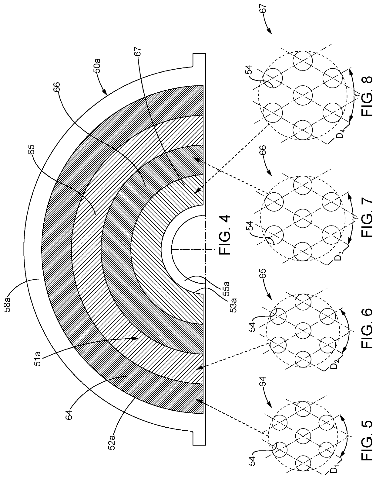
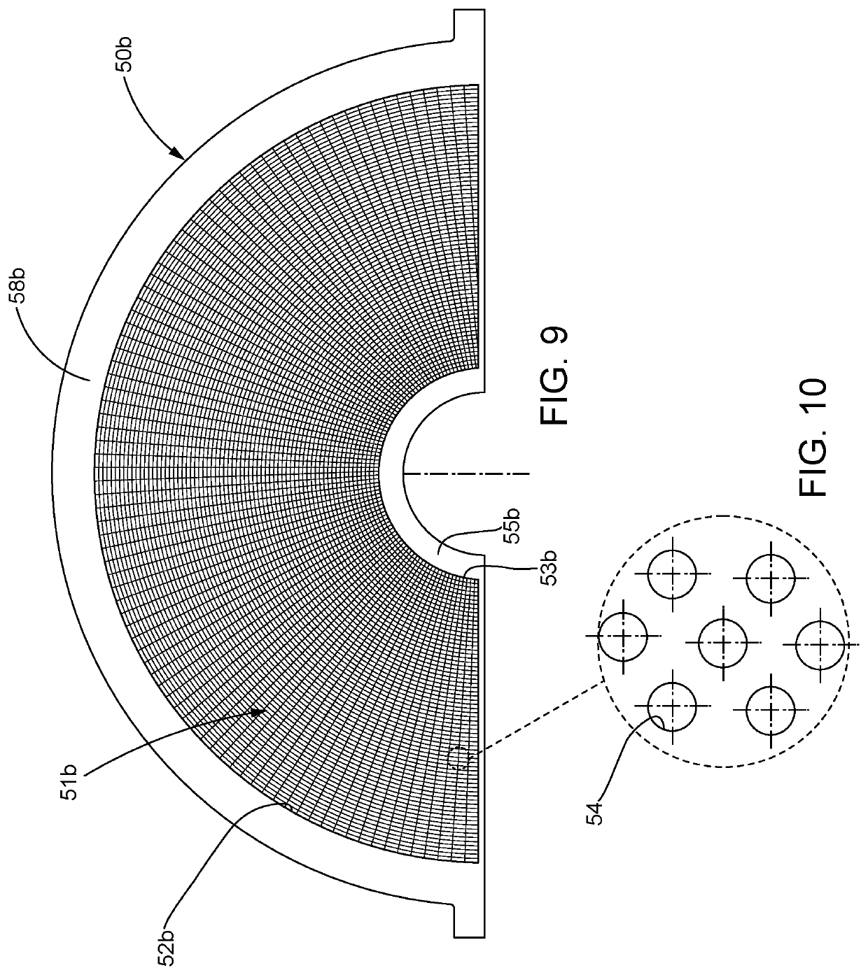
[0010]Disclosed herein are new “progressive open area percentage” screens that counter the uneven impeller forces from top to bottom, by varying the percentage of open area of the screens from top to bottom (or by varying the spacing distances between the openings). By changing the open area percentage, the slower impeller speeds near the bottom of the sidewall are compensated for with a lower open area percentage and longer spacings between openings, thereby giving the powder at the bottom of the screen exposure to more impeller rotations (i.e., longer residence times) before it passes through the openings. Further, the top or upper portion of the screen has more openings or a greater open area percentage because the higher rotational speed of the impeller at the top of the screen requires less exposure of the powder to the impeller and, hence, the need for a higher open area percentage and shorter spacings between openings. As a result, milling forces seen by the powders inside the milling chamber are evenly distributed across the entire height or length of the screen, resulting in more particles having similar sizes once milled and therefore narrower PSDs. The redesigned screen opening (hole) patterns increase the open area percentage near the top of the sidewall by up to 50% over traditional conical screens, thereby reducing the residence time inside the milling chamber, reducing heat generation and improving capacity.
[0011]In addition, to address the clean-in-place (CIP) requirement, the disclosed conical mills incorporate an impeller with a captured O-ring configuration and redesigned impeller cross arms ensuring full cleaning coverage of all powder-contact surfaces without the need to open the equipment to clean manually. Furthermore, complete containment of powders and cleaning solution is achieved inside the milling chamber via two O-rings, located above and below the screen's contact points with the feed chute and the housing. This ensures that powders during milling are only present in the internal contact surface areas and cleaning solutions cannot escape or be trapped in crevices after a cleaning cycle.
[0012]The disclosed conical mill employs non-metallic gears inside the gearbox, eliminating the need to use grease to lubricate. The gearbox is isolated from the product contact zone with the use of seals. These seals make positive contact with the rotating shaft to ensure that no product can penetrate the gearbox and no grease / lubricant can escape the gearbox and contaminate the powders being milled. To avoid the use of grease or lubricant in the gearbox altogether, the gearbox may employ non-metallic composite gears.
[0024]In any one or more of the embodiments described above, the impeller includes a lower base disposed at the bottom of the sidewall of the screen, which connects to an output shaft that extends through the bottom of the sidewall of the screen. The base connects to at least one milling member that extends from the top to the bottom of the sidewall of the screen. The output shaft connects to an output gear. The output gear meshes with an input gear. The input gear connects to an input shaft and the input shaft connects to a motor. In such an embodiment, the input gears are fabricated from non-metallic composite materials. In a further refinement of this concept, the output shaft and at least part of the input shaft are disposed within a gearbox, which sealably connects to the housing of the conical mill. Further, the gearbox includes no lubricant because the use of non-metallic composite materials for the input gears eliminates the need for lubricant.

Problems solved by technology

As a result, the energy imparted to the solid product or powder is not consistent from the top to the bottom of the screen.
Excessive amounts of particles falling above or below the target PSD can cause tableting defects and are sometimes removed or discarded, resulting in waste.
Further, the disposal of at least some pharmaceutical products requires special handling due to environmental regulations that increase the cost of the product or the loss associated with the production of particles that fall outside of the target PSD.
Further, because the production of powders may create an inhalation hazard, and a particularly acute hazard when it comes to some pharmaceutical compounds, the milling chamber must provide adequate containment of the milled powder and any dust created by the milling process.
Finally, conical mills can generate substantial noise during operation, which requires operators to wear ear protection.
With a manufacturer operating several or dozens of conical mills in one area of facility, noise generation from conical mills can be problematic.

Method used


Image

  • High efficiency conical mills
  • High efficiency conical mills
  • High efficiency conical mills

Examples


Embodiment Construction

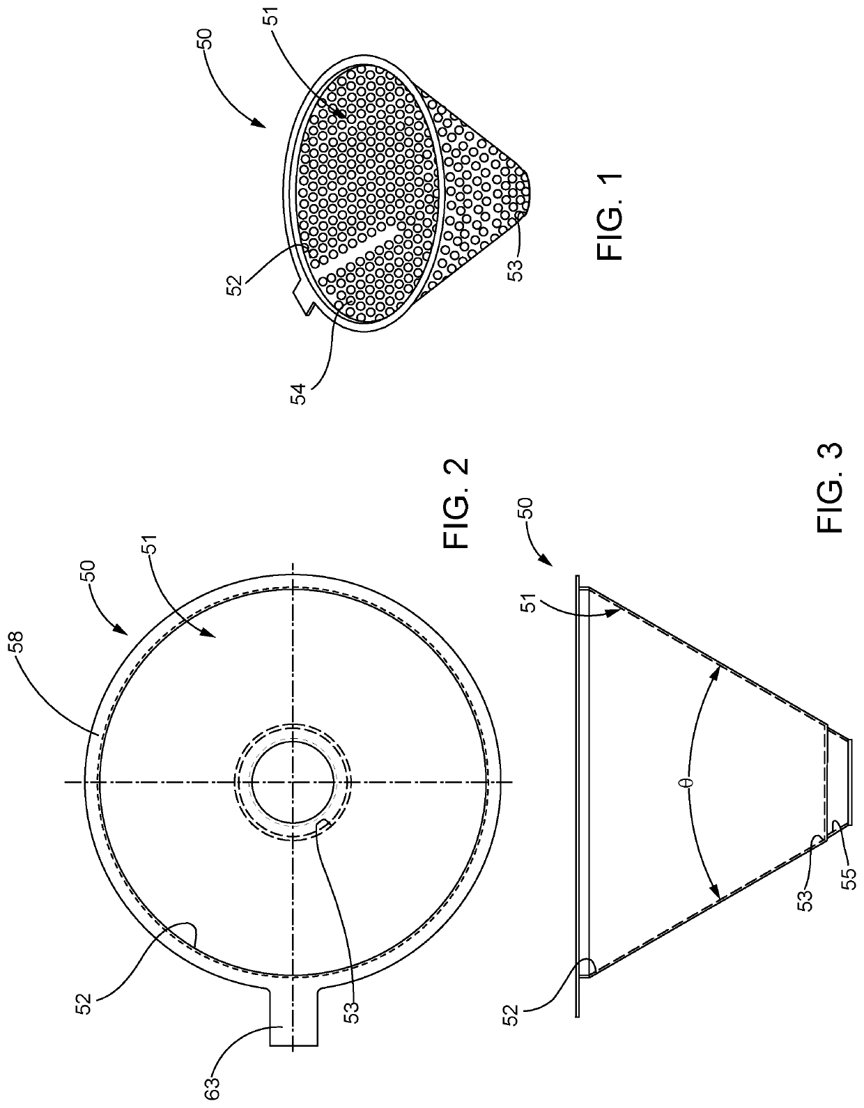
[0070]FIGS. 1-3 generally illustrate the configuration of a frusto-conical screen 50 for use in the conical mill 62 illustrated in FIGS. 23-28. The screen 50 includes a tapered sidewall 51 that includes a wider top 52 and a narrower bottom 53. The tapered sidewall 51 includes a plurality of openings or openings 54 that are of a uniform size. Typically, the angle θ between diametrically opposed portions of the tapered sidewall 51 is about 60°, but the exact geometry of the screen 50 may vary as will be apparent to those skilled in the art. The bottom 53 connects to another frusto-conical bottom section 55 for receiving the lower end 56 of the impeller 57 illustrated in detail in FIGS. 17-20. The screen 50 also includes an outer flange 58 for supporting the screen 50 within the housing 61 of the conical milling 62 as illustrated in FIGS. 24-25. The screen 50 may also include a tab 63 for ease of handling.

[0071]FIG. 4 illustrates a partial top view of another disclosed screen 50a that ...


PUM


Abstract

Screens for conical mills and an improved gearbox and housing for such conical mills are shown and described. The screens are frusto-conically-shaped and include a tapered sidewall with a plurality of openings in the sidewall that may be of uniform size. Each opening is separated from adjacent openings by spacing distances which are shorter at the top of the tapered sidewall and longer at the bottom of the tapered sidewall to thereby reduce the residence time of the powder being milled at the top of the tapered sidewall and to increase the residence time of the powder being milled at the bottom of the tapered sidewall.

Description

RELATED APPLICATION DATA[0001]This application is a national phase application of and claims priority to International Application No. PCT / 162016 / 001130 filed Jul. 12, 2016, which claims priority to U.S. Provisional Patent Application No. 62 / 208,281 filed Aug. 21, 2015, which are hereby all incorporated herein by reference.BACKGROUNDTechnical Field[0002]This disclosure relates to conical mills used to reduce the particle size of granular materials. More specifically, this disclosure relates to the conical screens used in such conical mills, which include a hole pattern that varies from the top to the bottom of the sidewall for narrower particle size distributions, reduced heat generation and increased capacity. The disclosed conical mills may be cleaned without disassembly and the disclosed conical mills feature lubricant-free gearboxes, which reduce the risk of product contamination.Description of the Related Art[0003]Conical mills are widely used in the production of powders used ...

Claims


Application Information

Patent Timeline
Patent Type & Authority Patents(United States)
IPC IPC(8): B02C18/06B02C23/16
CPCB02C18/062B02C23/16B02C2023/165
Inventor SANGUESA, WILFWATSON, BARRYVERBERNE, JEFFWATSON, SEAN
Owner QUADRO ENG CORP
Learn More