Exciting method for elastic vibration member and vibratory driving device

a technology of elastic vibration and driving device, which is applied in the direction of generator/motor, optical element, instruments, etc., can solve the problems of increasing resonant frequency, limiting the shape of elastic vibration member and difficulty of design, and undesirable invitation to further increase in resonant frequency, etc., to ensure the flexibility of shape, size and material choice, and ensure the effect of vibrating circularly or elliptically. , the design is easy and flexibl

Inactive Publication Date: 2009-04-21
SONY CORP
View PDF16 Cites 16 Cited by
  • Summary
  • Abstract
  • Description
  • Claims
  • Application Information

AI Technical Summary

Benefits of technology

[0012]The present invention provides a vibratory driving device which can be designed easily and flexibly at a low cost.
[0017]According to an embodiment of the present invention, the drive signals having the same frequency and a phase difference are respectively supplied to the two support members to thereby excite the elastic vibration member, so that the elastic vibration member can be reliably vibrated circularly or elliptically.
[0018]Accordingly, it is necessary to combine two vibration modes, but a stretch mode as a single vibration mode is used in the present invention, so that the vibratory driving device can be designed easily and flexibly, and it is possible to ensure the flexibility of choice of the shape, size, and material of the elastic vibration member.
[0019]Further, since the shape and size of the elastic vibration member are less limited, a cost reduction can be expected.
[0020]Further, since the projecting portion and the driven member are kept in pressure contact with each other by the pressure applying means, the motion of the driven member due to the circular or elliptical vibration of the projecting portion can be reliably produced.

Problems solved by technology

Further, it is not ensured that the frequency ranges of these two bending vibration modes are adjacent to each other.
To make the resonant frequencies in the two bending vibration modes equal to each other, adjustment (degeneration) of the size, shape, thickness, etc. of the elastic vibration member may be required, causing a limitation to the shape of the elastic vibration member and a difficulty of design.
Accordingly, the use of the longitudinal vibration mode (vertical vibration) generally causes an increase in resonant frequency, which is impractical.
Further, when the longitudinal size of the elastic vibration member is reduced, a further increase in resonant frequency is undesirably invited.
Further, a limitation to the shape and size of the elastic vibration member and a dimensional accuracy in working the elastic vibration member are necessary for the excitation of the two vibration modes at near frequencies, causing an increase in cost.

Method used


Image

  • Exciting method for elastic vibration member and vibratory driving device
  • Exciting method for elastic vibration member and vibratory driving device
  • Exciting method for elastic vibration member and vibratory driving device

Examples


first preferred embodiment

[0033]Preferred embodiments of the present invention will now be described with reference to the attached drawings.

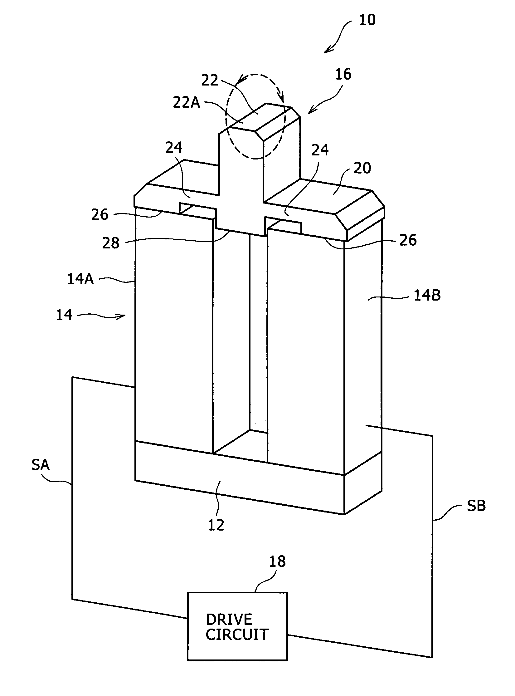
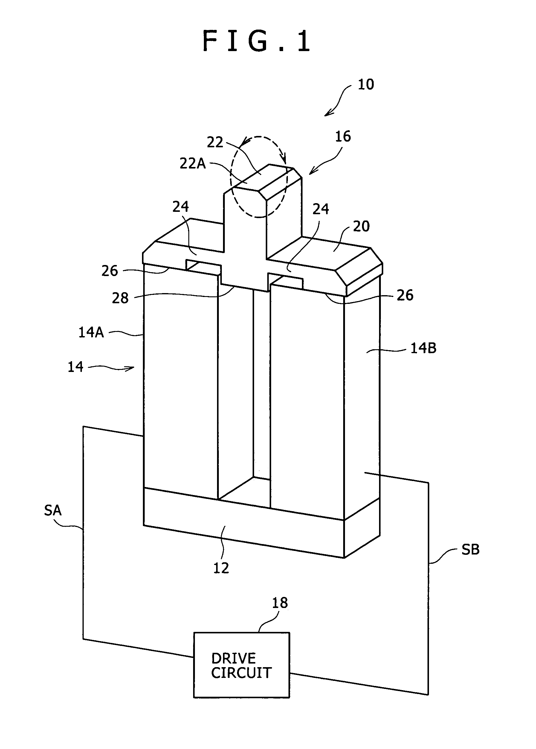
[0034]FIG. 1 is a perspective view of a vibratory driving device 10 according to the first preferred embodiment.

[0035]As shown in FIG. 1, the vibratory driving device 10 includes a base 12, two support members 14, an elastic vibration member 16, and a drive circuit 18 (corresponding to the control section in the present invention).

[0036]The base 12 is an elongated rectangular plate member and has an upper surface having an area enough to mount the lower ends of the two support members 14.

[0037]The base 12 is formed of a metal material such as brass.

[0038]Each of the two support members 14 is a columnar member having a rectangular cross section and a height larger than the length of each side of the rectangular cross section. The sectional shape of each support member 14 is not limited to such a rectangular shape as in this preferred embodiment, but any other shapes such...

second preferred embodiment

[0084]A second preferred embodiment of the present invention will now be described with reference to FIG. 5.

[0085]In the second preferred embodiment, the vibratory driving device 10 is applied to a driven member 30, thereby constructing a mechanism for linearly reciprocating the driven member 30.

[0086]FIG. 5 is a partially sectional elevation of the vibratory driving device 10 and its associated parts constituting the above mechanism according to the second preferred embodiment. In FIG. 5, substantially the same parts or members as those of the first preferred embodiment are denoted by the same reference numerals.

[0087]As shown in FIG. 5, the driven member 30 is a flat elongated plate member supported so as to be reciprocatable in its longitudinal direction.

[0088]A sliding surface member 31 is formed on the upper surface of the driven member 30. The sliding surface member 31 is formed of a material having a low coefficient of friction, such as a resin material.

[0089]A holding stay 3...

third preferred embodiment

[0107]A third preferred embodiment of the present invention will now be described with reference to FIG. 6.

[0108]The third preferred embodiment is different from the second preferred embodiment in the point that the driven member 30 is not linearly moved, but is rotationally moved.

[0109]FIG. 6 is a perspective view of the vibratory driving device 10 and the driven member 30 according to the third preferred embodiment.

[0110]As shown in FIG. 6, the driven member 30 is a flattened annular member having an axial end surface 3010 as the lower surface of the driven member 30, and the driven member 30 is supported so as to be rotatable about an axis L1.

[0111]The vibratory driving device 10 shown in FIG. 6 is held in such a manner that the upper end 22A of the projecting portion 22 abuts against the axial end surface 3010 of the driven member 30 at a position near the outer circumference thereof in the condition where the first and second support members 14A and 14B extend in a direction pe...


PUM


Abstract

Disclosed herein is an exciting method for an elastic vibration member which may include arranging two support members each formed from an electro-mechanical energy transducer; supporting the elastic vibration member to the two support members at their front ends; and supplying drive signals having the same frequency and a phase difference to the two support members, circularly or elliptically vibrating the elastic vibration member.

Description

CROSS-REFERENCE TO RELATED APPLICATIONS[0001]This application claims priority from Japanese Patent Application No. JP 2006-002111 filed in the Japanese Patent Office on Jan. 10, 2006, the entire content of which is incorporated herein by reference.BACKGROUND OF THE INVENTION[0002]1. Field of the Invention[0003]The present invention relates to an exciting method for an elastic vibration member and a vibratory driving device.[0004]2. Description of the Related Art[0005]In the past proposed is an exciting method for an elastic vibration member in a vibratory driving device for linear or rotational motion.[0006]For example, a first technique in the related art mentioned below is proposed. This technique includes an elastic vibration member, a drive member having at least two electrodes and an electro-mechanical energy transducer for exciting the elastic vibration member by applying drive voltages having the same frequency and two phases to these two electrodes, and a driven member kept ...

Claims


Application Information

Patent Timeline
Patent Type & Authority Patents(United States)
IPC IPC(8): H01L41/08
CPCG02B27/08H02N2/0025H02N2/026H02N2/028H02N2/103A61H39/08A61H39/083
Inventor MORI, HIROYUKI
Owner SONY CORP
Why Eureka
Try Eureka