

Sanitary plunger
- Summary
- Abstract
- Description
- Claims
- Application Information
AI Technical Summary
Benefits of technology
Problems solved by technology
Method used
Image

Examples
Embodiment Construction
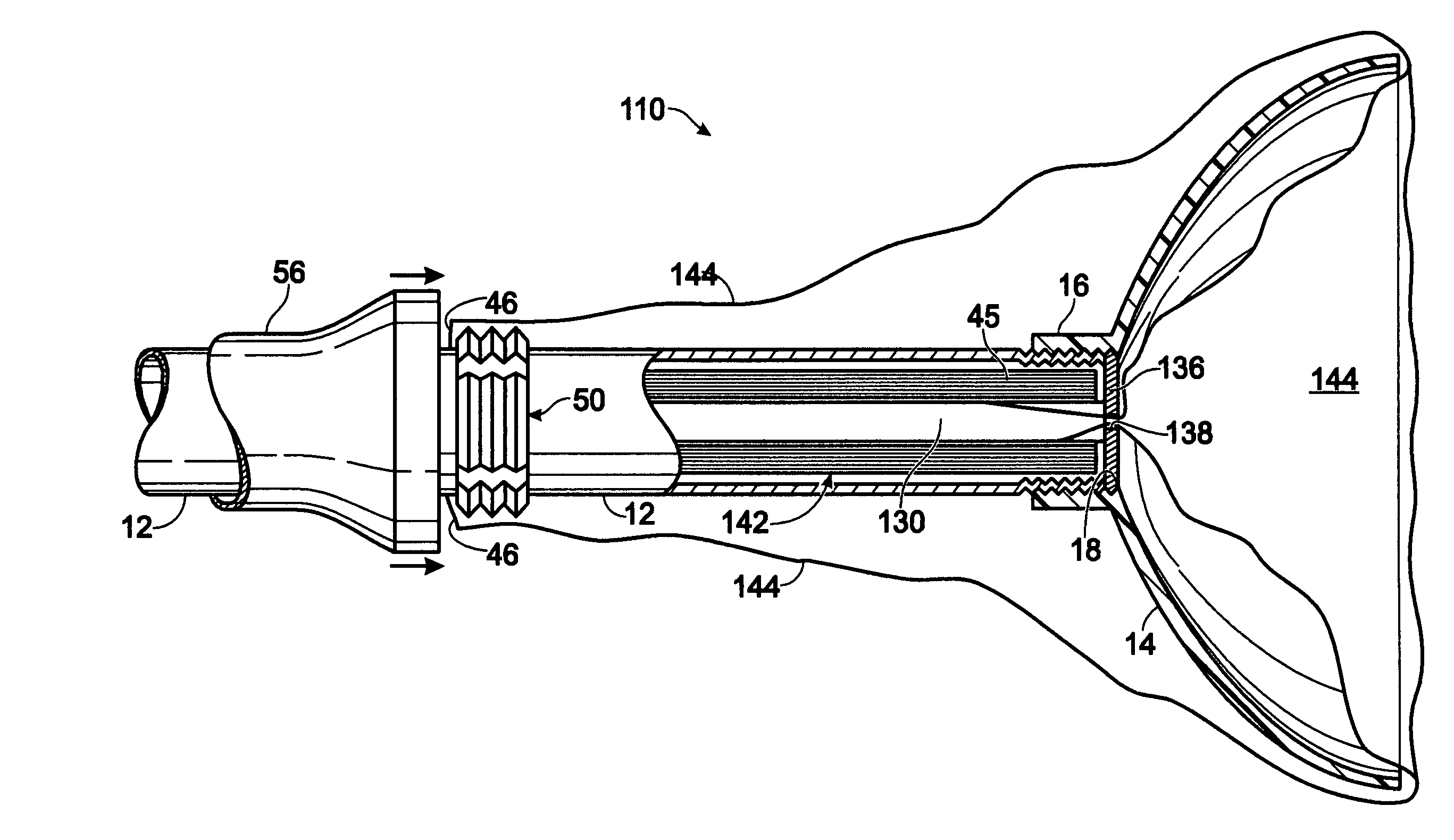
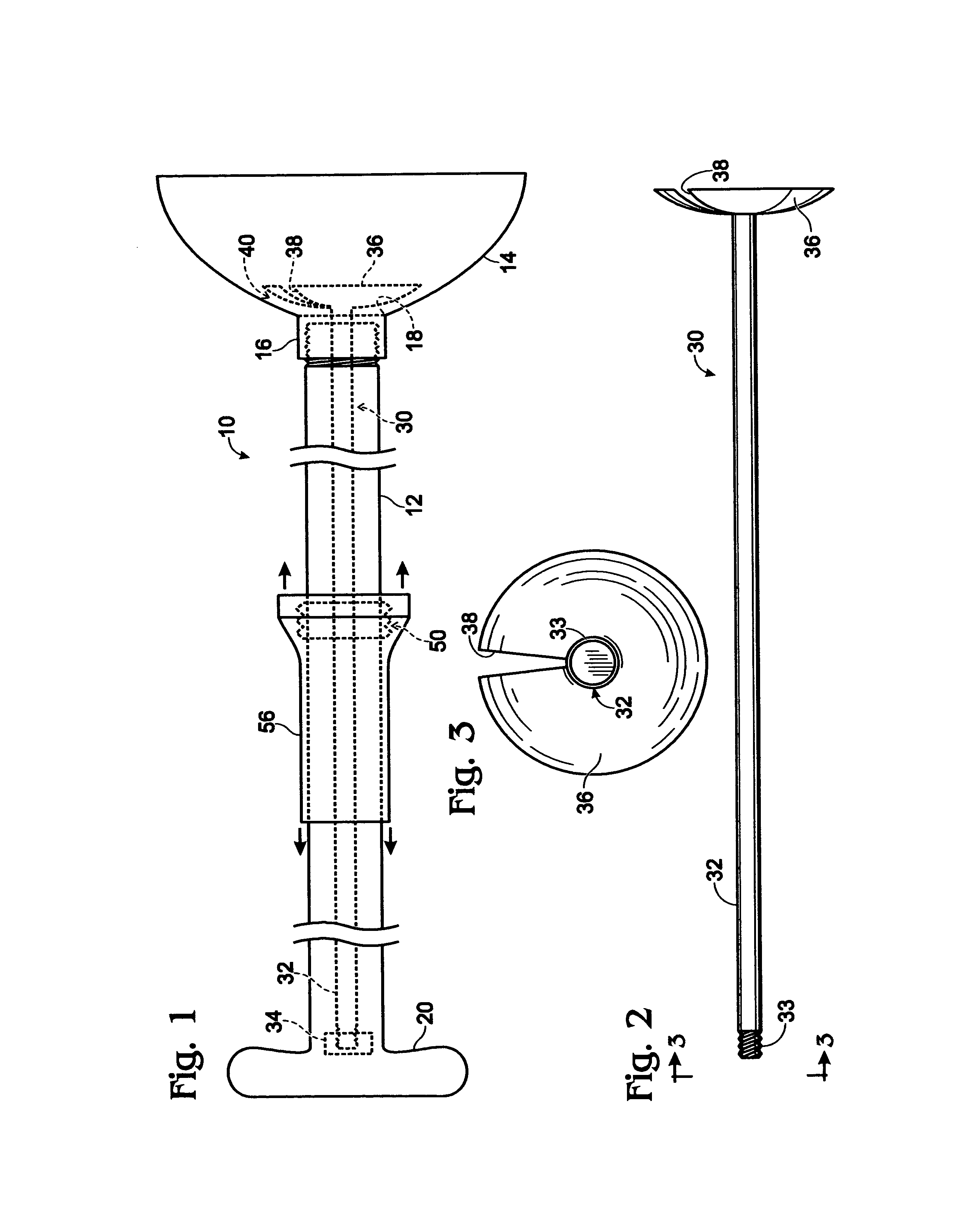
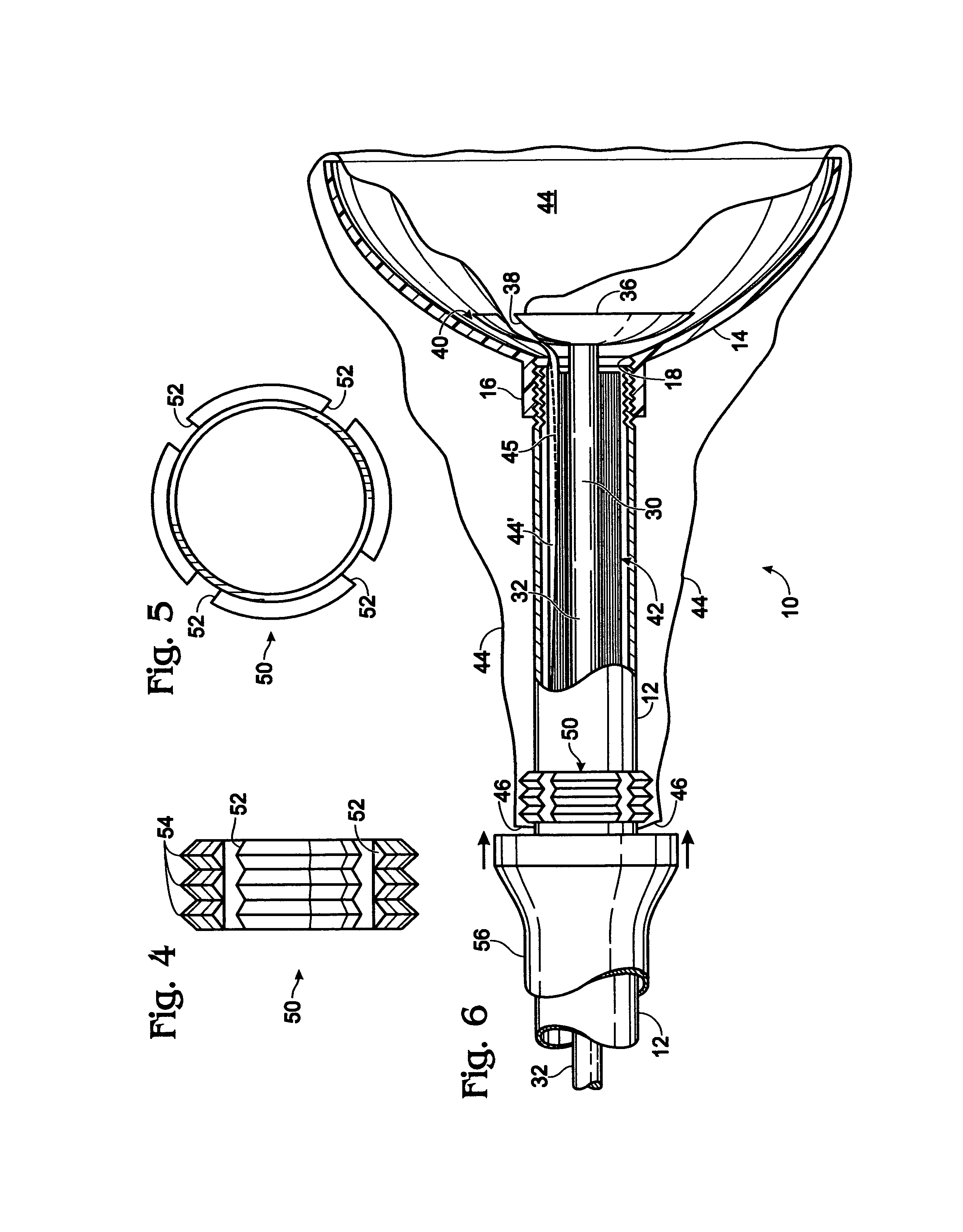
[0016]The sanitary plunger 10 of the present invention includes a tubular handle shaft 12 and a flexible force cup 14 attached to the lower end of tubular handle shaft 12. The flexible force cup 14 is preferably made of rubber or rubber-like material of the type with which force cups are conventionally made. Force cup 14 has a handle receiving tubular extension 16 extending outwardly from the center thereof. The interior of tubular handle shaft 12 communicates with the interior of flexible force cup 14 via circular opening 18 that is coaxial with tubular extension 16. A hand grip 20 is attached to the upper end of tubular handle shaft 12.
[0017]A first embodiment has a distributor means that includes a spindle 30 and a cup-shaped spreader member 36.
[0018]Spindle 30 includes a spindle shaft 32 that is positioned within tubular handle 12 along the longitudinal axis thereof.
[0019]The upper end of spindle shaft 32 is threaded at 33 and adapted to be screwed into centrally threaded spider...
PUM
 Abstract
Description
Claims
Application Information