Tubing fitting

a technology of tubing and fittings, applied in the field of surgical systems, can solve the problems of increasing instrumentation sophistication and complexity, and the need for new fittings that would be physically impossible to connect to standard and/or “oversized” luer fittings

Active Publication Date: 2009-04-28
ALCON INC
View PDF16 Cites 78 Cited by
  • Summary
  • Abstract
  • Description
  • Claims
  • Application Information

AI Technical Summary

Benefits of technology

[0009]One aspect of the present invention is a tubing fitting for use in microsurgery including a female tubing fitting and a male tubing fitting. The female tubing fitting has an external surface with a pair of opposing projections disposed thereon and an internal bore. The male tubing fitting has a second internal bore and a collar at least partially surrounding the second internal bore. The collar has an internal surface with two pairs of opposing sloping ramps disposed thereon. The pairs of opposing sloping ramps are arranged so as to create a pair of opposing spaces for removably receiving the pair of opposing projections. When the pair of opposing projections are disposed in the pair of opposing spaces, the male tubing fitting may be sealingly locked into the female tubing fitting by rotating the collar. The pairs of opposing sloping ramps and the pair of opposing spaces create a geometry that prevent engagement with conventional luer and CPC fittings.

Problems solved by technology

As time passed and ophthalmic surgical instrumentation grew in sophistication and complexity, the need arose for new fittings that would be physically impossible to connect to standard and / or “oversized” luer fittings.

Method used


Image

  • Tubing fitting
  • Tubing fitting
  • Tubing fitting

Examples


Embodiment Construction

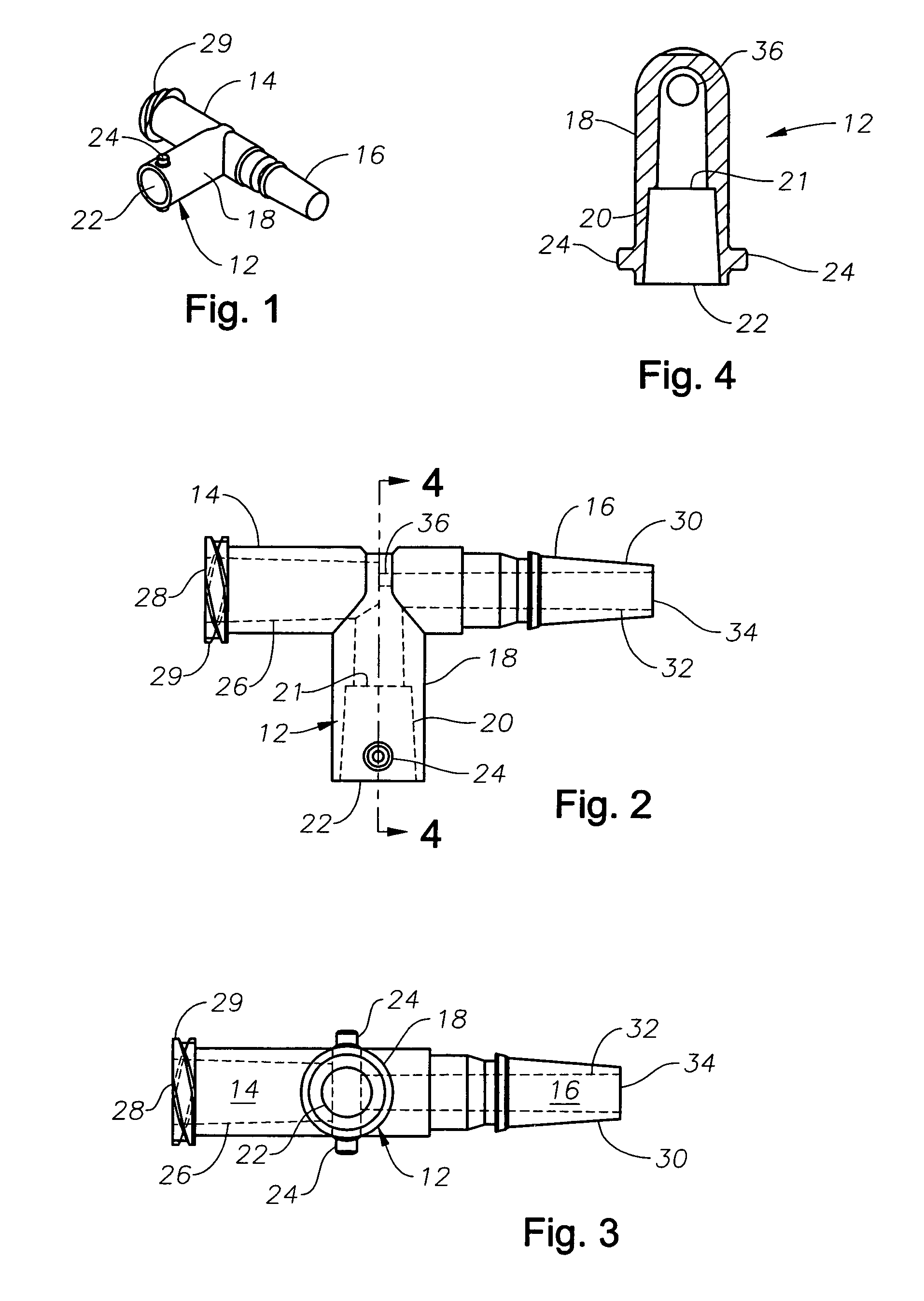
[0018]The preferred embodiments of the present invention and their advantages are best understood by referring to FIGS. 1 through 7 of the drawings, like numerals being used for like and corresponding parts of the various drawings.

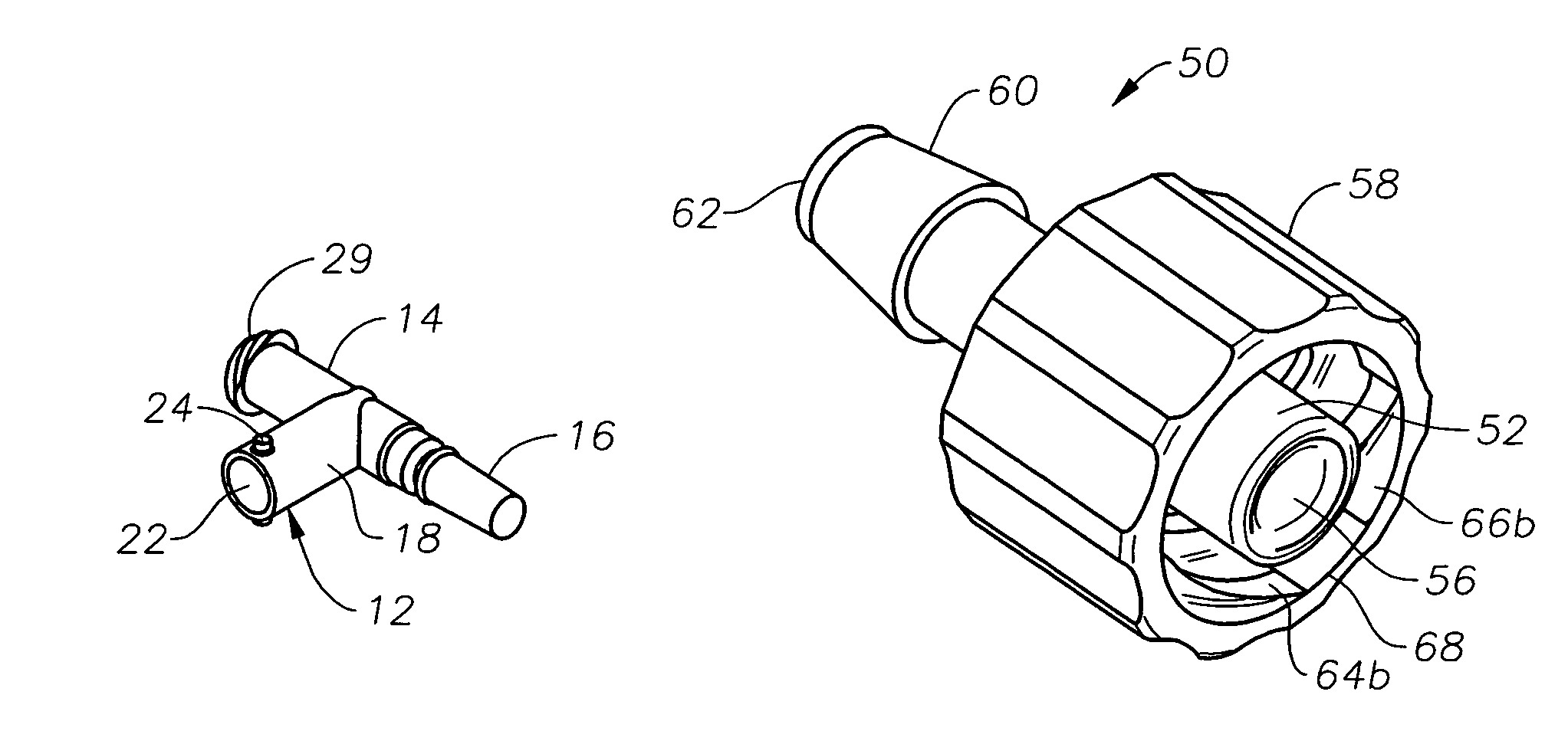
[0019]As shown in FIGS. 1-4, female tubing fitting 12 is shown having a “T-connector” configuration. In this configuration, female tubing fitting 12 has a threaded fitting 14 and a male plug 16. Female tubing fitting 12 preferably includes an external surface 18, an internal bore 20 having a luer taper and a shelf 21, and an opening 22. Internal bore 20 is sized so as to prevent engagement with a conventional oversized male luer slip fitting. Shelf 21 prevents engagement with a conventional male luer slip fitting. External surface 18 includes a pair of opposed projections 24. Opposed projections 24 have a geometry and size that prevent engagement with conventional male luer lock and CPC fittings. Threaded fitting 14 preferably has an internal bore 26 havin...


PUM


Abstract

A tubing fitting for use in microsurgery including a female tubing fitting and a male tubing fitting. The female tubing fitting has an external surface with a pair of opposing projections disposed thereon and an internal bore. The male tubing fitting has a second internal bore and a collar at least partially surrounding the second internal bore. The collar has an internal surface with two pairs of opposing sloping ramps disposed thereon. The pairs of opposing sloping ramps are arranged so as to create a pair of opposing spaces for removably receiving the pair of opposing projections.

Description

[0001]This application claims the priority of U.S. Provisional Application No. 60 / 635,599 filed Dec. 13, 2004.FILED OF THE INVENTION[0002]The present invention generally pertains to microsurgery and more particularly to tubing fittings for use during ophthalmic surgery.DESCRIPTION OF THE RELATED ART[0003]A variety of surgical systems are used in ophthalmic surgery. For example, such systems may include a surgical console, accessories (e.g. footswitch, reusable handpieces), and various consumables. The consumables typically include tubing sets that connect to the console and provide a pathway from the console in the non-sterile field to a surgical handpiece or other device that is used in and remains in the sterile field. A tubing fitting is typically used to fluidly couple one end of a piece of tubing to the console, and a second tubing fitting is typically used to fluidly couple another end of the piece of tubing to a surgical device.[0004]Luer fittings are used extensively on medi...

Claims


Application Information

Patent Timeline
Patent Type & Authority Patents(United States)
IPC IPC(8): F16L21/00
CPCA61M39/10A61M2205/6045Y10S604/905
Inventor STEPPE, DENNIS L.
Owner ALCON INC
Why Eureka
Try Eureka