Drive control apparatus for forklift

a control apparatus and forklift technology, applied in electrical control, instruments, gearing, etc., can solve the problems of inability to prevent the vehicle from being unstable, engine control not timely performed, and unstable starting of the vehicl

Active Publication Date: 2009-04-28
TOYOTA IND CORP
View PDF12 Cites 28 Cited by
  • Summary
  • Abstract
  • Description
  • Claims
  • Application Information

AI Technical Summary

Benefits of technology

[0006]Accordingly, it is an objective of the present invention to provide a drive control apparatus for a forklift that prevents the forklift from being started in a state that is likely to make the driving of the forklift unstable.

Problems solved by technology

In a sudden acceleration of a vehicle, the technique for limiting acceleration according to the publication No. 2001-163597 may not be able to prevent the vehicle from being unstable.
Therefore, in the acceleration control disclosed in Japanese Laid-Open Patent Publication No. 2001-163597, the engine control is not timely performed to deal with such an abrupt change in acceleration.
As a result, the vehicle is abruptly started, which is likely to cause the driving of the vehicle at the start to be unstable.
Thus, even if the control disclosed in Japanese Laid-Open Patent Publication No. 9-24751 is applied to a forklift, the driving stability at the start is not fully ensured.
However, in a case of harsher loading condition, for example, when a load is held at a relatively high position, the stability may not be ensured.
As a result, depending on the load state, the reduction of the engine speed cannot be performed sufficiently early (engine control is not sufficiently early).
This makes the driving at the start unstable.

Method used


Image

  • Drive control apparatus for forklift
  • Drive control apparatus for forklift
  • Drive control apparatus for forklift

Examples


first embodiment

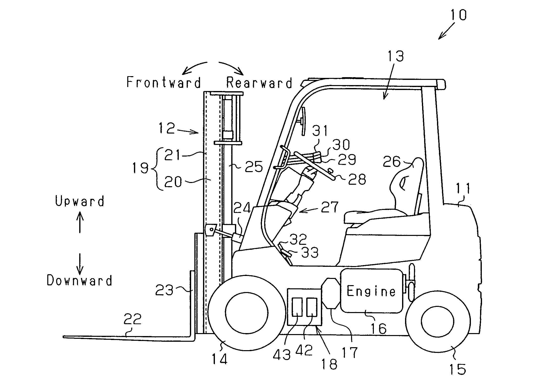
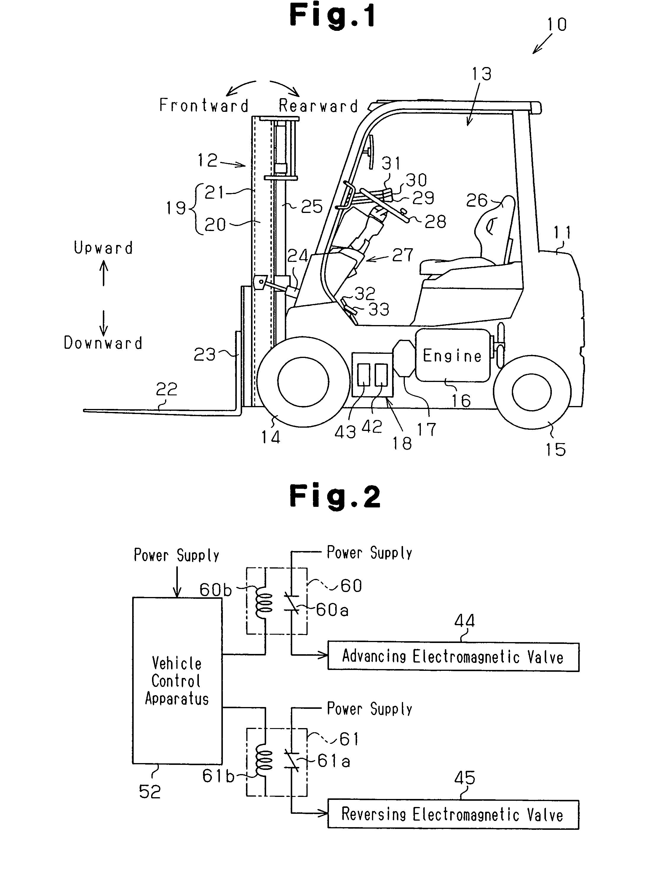
[0034]A drive control apparatus CD for use in a forklift 10 according to the present invention will now be described with reference to FIGS. 1 to 9. In the following, the direction in which a driver of the forklift 10 is defined as a forward direction. The backward, upward, downward, leftward, and rightward directions are defined with reference to the forward direction.

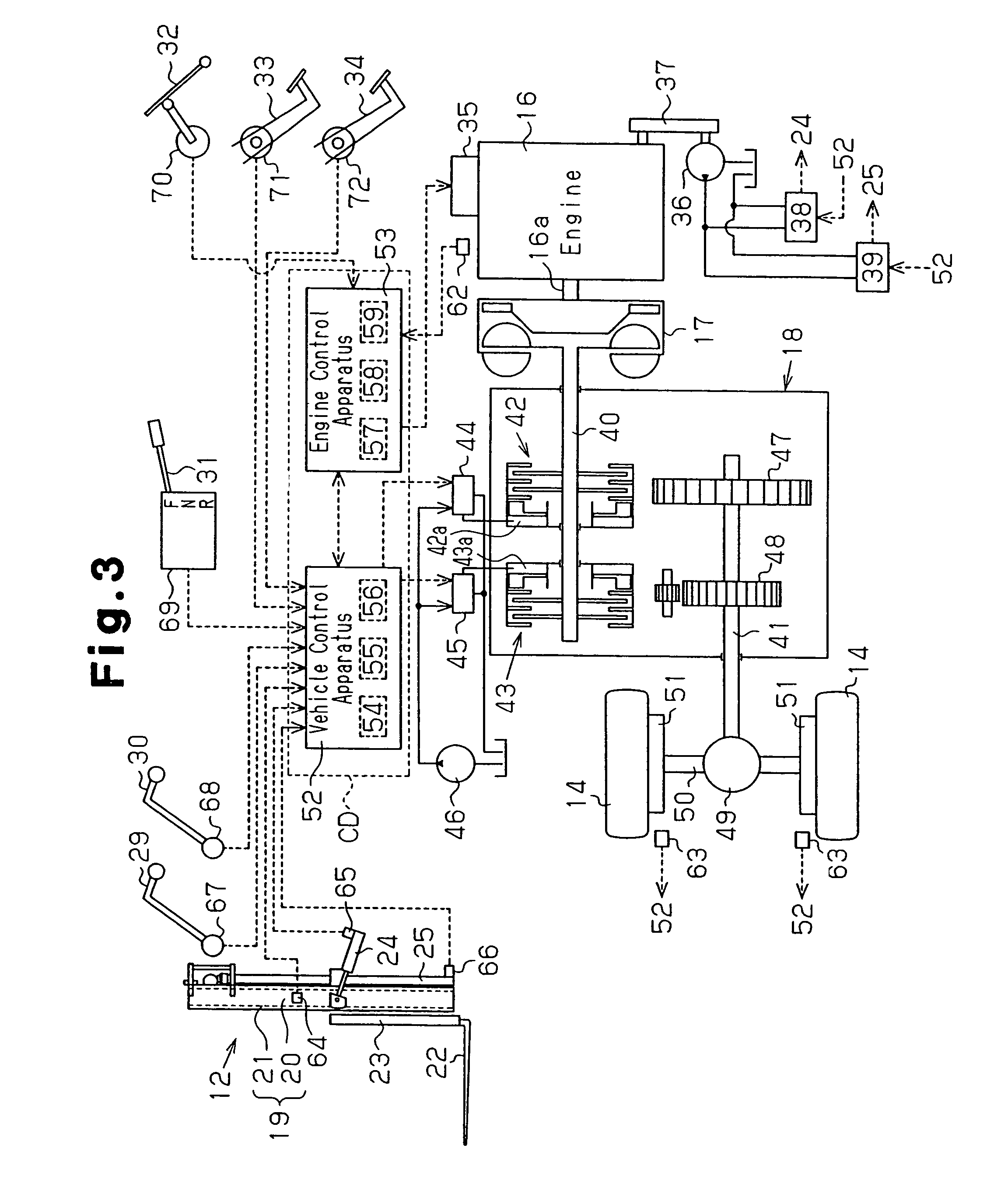
[0035]FIG. 1 is a side view of the forklift 10. As shown in FIG. 1, the forklift 10 includes a loading device 12 at a front portion of a vehicle body 11. A cab 13 is formed in a center portion of the vehicle body 11. Drive wheels (front wheels) 14 are located in front and lower portions of the vehicle body 11, and steered wheels 15 are provided in rear and lower portions of the vehicle body 11. The vehicle body 11 also mounts a transmission 18 having a torque converter 17. The torque converter 17 forms a power transmission mechanism. An engine 16 is coupled to the drive wheels 14 by way of the transmission 18 having t...

second embodiment

[0096]the present invention will now be described with reference to FIG. 11. In the following embodiments, explanations of the same components of the already described embodiment will be omitted or simplified.

[0097]In this embodiment, when the driving force is forcibly disconnected, the disconnection state is cancelled by operation of the driver. Specifically, performing the ON operation of the accelerator pedal 32 after performing the OFF operation of the accelerator pedal 32 is set as a cancellation condition to cancel the disconnection state. FIG. 11 shows a start control process executed by the CPU 54 of the vehicle control apparatus 52 in this embodiment.

[0098]The start control process of this embodiment will be described with reference to FIG. 11. In FIG. 11, the same reference numerals are given to those steps that are the same as the corresponding steps in the start control process (FIG. 8) of the first embodiment. In the following, the redundant explanations for the same pr...

seventh embodiment

[0142]the present invention will now be described with reference to FIGS. 17 to 20. In the following embodiments, explanations of the same components of the already described embodiments will be omitted or simplified.

[0143]In the previous embodiments, the starting is assumed to be performed on a flat ground, and uphill starting is not considered. That is, when a sudden start prevention control is executed, reduction of the engine speed to a level equal to or less than a certain value (limitation canceling engine speed Mb) is detected, and the forklift is permitted to travel by canceling the driving force disconnection state and the engine speed reduction control state. However, if the limitation canceling engine speed Mb is set high to prevent roll back on an uphill road, there will be a problem in starting on a flat ground. That is, as shown in FIG. 17, after the sudden start prevention control is started at time t0 at which the engine speed is the limitation engine speed Ma, when ...


PUM


Abstract

A load determining section of a drive control apparatus for forklift determines a load state related to a loading attachment. In a case where a connection determining section determines switching to a connection state, if the load state determined by the load determining section requires that driving of a vehicle body be limited, a disconnection control section forcibly disconnects a transmission of a driving force to a drive wheel. Thus, the forklift is prevented from being started in a state that is likely to make the driving of the forklift unstable.

Description

BACKGROUND OF THE INVENTION[0001]The present invention relates to a drive control apparatus for controlling driving of a forklift.[0002]Conventionally, forklifts are widely used as industrial vehicles for handling loads (picking up and placing of loads) in plants. Due to its characteristic usage, the driving stability of this type of forklift greatly varies depending on the load state. For example, the center of gravity of the vehicle is shifted and the driving stability varies between a state of carrying no loads and a state of carrying a load. When carrying a load, the driving stability varies depending on the weight of the load, the height of the fork on which the load is mounted, the tilt angle of the fork. Thus, conventionally, a technique for limiting the driving of a forklift in accordance with the load state to improve the driving stability of the vehicle is disclosed in Japanese Laid-Open Patent Publication No. 2001-163597. In the publication No. 2001-163597, the minimum va...

Claims


Application Information

Patent Timeline
Patent Type & Authority Patents(United States)
IPC IPC(8): F16H45/02
CPCB60K28/08B66F9/07572B66F17/003B60Y2200/15Y10T477/747Y10T477/735Y10T477/745Y10T477/743Y10T477/753B66F9/24B66F9/06
Inventor OKA, HIDENORIYAMADA, TADASHIKAMIYA, TOSHIKAZUTAKAHASHI, MASAYUKIHASEGAWA, KIMIHIDEKOBAYASHI, HIROKAZU
Owner TOYOTA IND CORP
Why Eureka
Try Eureka