Internal combustion engine having a crankcase ventilation device, and method for monitoring a crankcase ventilation device

Inactive Publication Date: 2016-04-07
HENGST WALTER +1
View PDF0 Cites 17 Cited by
  • Summary
  • Abstract
  • Description
  • Claims
  • Application Information

AI Technical Summary

Benefits of technology

[0018]So that a separate additional evaluation unit does not have to be manufactured and installed for the crankcase ventilation device, preferably the evaluation unit is an electronic engine control module that is allocated to the internal combustion engine and is already present in current internal combustion engines, and that can perform, after corresponding programming, the evaluation of the measurement values of the difference pressure sensor or sensors of the crankcase ventilation device. Because the engine control module acts immediately on the functions of the internal combustion engine, when improper functioning of the crankcase ventilation device is determined by the engine control module a corresponding warning signal can be outputted to an operator of the internal combustion engine, and/or a starting of th

Problems solved by technology

It has been discovered that the values of the pressure difference that occur during proper functioning and operation of the crankcase ventilation device differ recognizably from the values of the pressure difference that occur during improper function

Method used


Image

  • Internal combustion engine having a crankcase ventilation device, and method for monitoring a crankcase ventilation device
  • Internal combustion engine having a crankcase ventilation device, and method for monitoring a crankcase ventilation device
  • Internal combustion engine having a crankcase ventilation device, and method for monitoring a crankcase ventilation device

Examples


Example

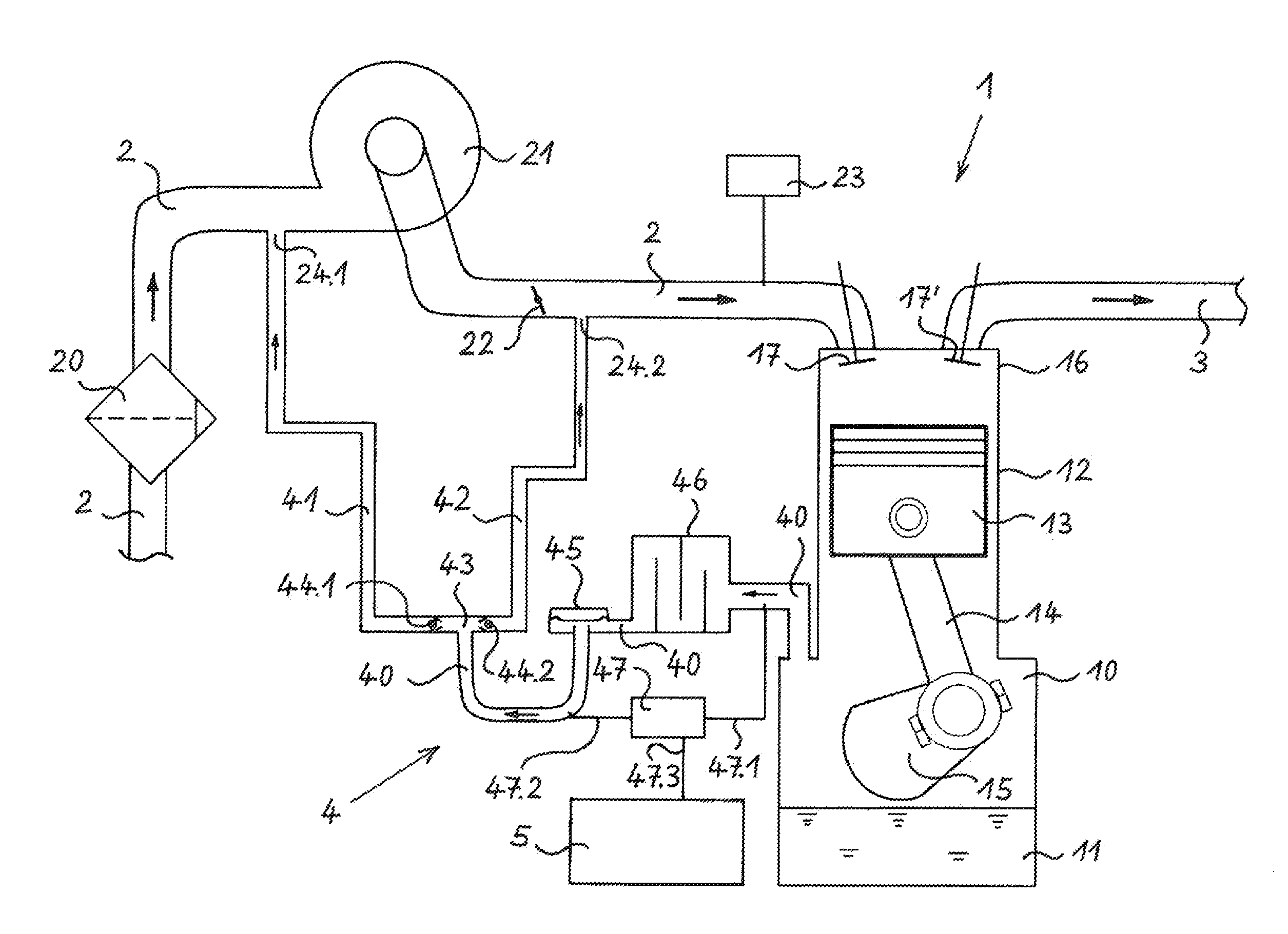
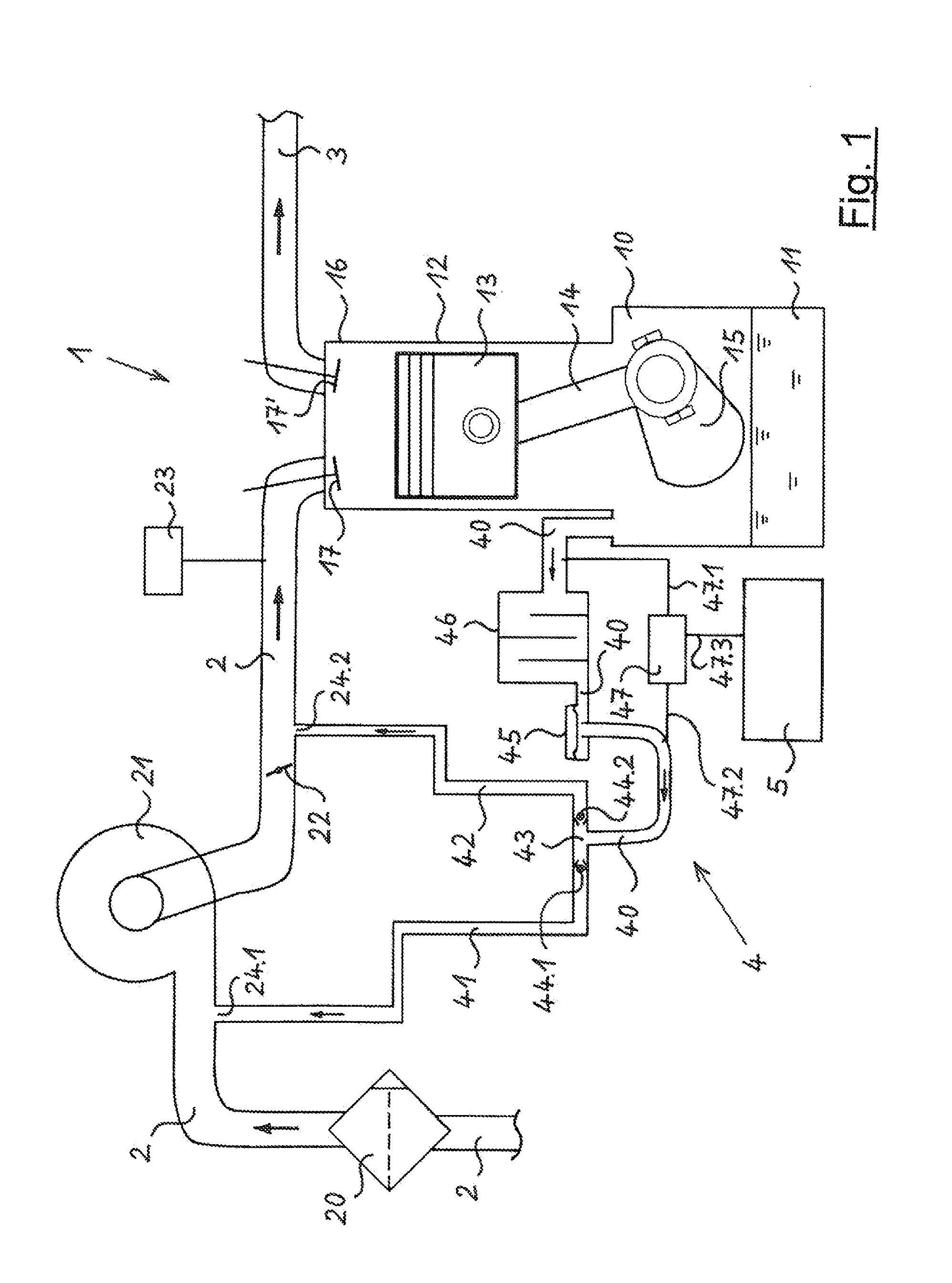
[0027]FIG. 1 shows an internal combustion engine 1 having a crankcase ventilation device 4 in a purely schematic representation. At the right in FIG. 1, a crankcase 10 of internal combustion engine 1 can be seen, whose lower part forms an oil sump 11 for the lubricant oil of internal combustion engine 1. In crankcase 10, crankshaft 15 is mounted, from which there goes out a connecting rod 14 connected at its upper end to a piston 13. Piston 13 is guided so as to be movable in the axial direction in a cylinder 12 of internal combustion engine 1. Above piston 13 there is situated a cylinder head 16 having an inlet valve 17 and outlet valve 17′.

[0028]At the left and at the top in FIG. 1, an intake air duct 2 is visible that leads to inlet valve 17 via an air filter 20 and a compressor 21 of a turbocharger or compressor. A throttle valve 22 is situated in intake air duct 2 between compressor 21 and inlet valve 17. An air mass sensor 23 is connected to the segment of intake air duct 2 be...


PUM


Abstract

An internal combustion engine having an intake air duct with a compressor, a throttle valve, and a crankcase ventilation device with a ventilation duct connected to a crankcase with a crankcase pressure regulating valve, the ventilation duct divided into a first ventilation duct branch connected to the intake air duct upstream from the compressor, and a second ventilation duct branch connected to the intake air duct downstream from the throttle valve. A pressure difference between the pressure in the crankcase or in the ventilation duct upstream from the crankcase pressure regulating valve on the one hand and the pressure in the ventilation duct downstream from the crankcase pressure regulating valve on the other hand is measured by, for example, a sensor, and an evaluation unit evaluates for a correct or incorrect functioning of the crankcase ventilation device and a corresponding item of information can be outputted.

Description

RELATED APPLICATIONS[0001]This application claims priority to German Patent Application No. 10 2014 114 397.3, filed on Oct. 2, 2014 and also claims priority to U.S. Provisional Patent Application Ser. No. 62 / 065,089 filed on Oct. 17, 2014, the entirety of both of which are incorporated herein by reference.FIELD OF THE INVENTION[0002]The present invention relates to an internal combustion engine having an intake air duct in the course of which there are situated a compressor of an exhaust gas turbocharger or compressor, and, downstream from the compressor, a throttle valve, and having a crankcase ventilation device that has a ventilation duct connected to the crankcase of the internal combustion engine, in the course of which duct there is situated a crankcase pressure regulating valve, the ventilation duct being divided, downstream from the crankcase pressure regulating valve, into two ventilation duct branches, a first ventilation duct branch being connected to the intake air duct...

Claims


Application Information

Patent Timeline
IPC IPC(8): F02M35/10
CPCF01M2013/0083F02M35/10222F01M11/00F01M13/0011F01M13/022F01M2013/0044F01M2013/027F01M2013/0472Y02T10/12
Inventor MARTUS, KEVINPOLLOCK, DAVEROELVER, MARTIN
Owner HENGST WALTER
Why Eureka
Try Eureka