Measuring device for detecting stresses of a bearing arrangement

a technology for detecting stresses and bearings, applied in the direction of instruments, force measurement by measuring optical property variation, force/torque/work measurement apparatus, etc., can solve the problem of complicated arrangement of this type, and achieve the effect of simple and inexpensiv

Inactive Publication Date: 2009-05-05
SCHAEFFLER TECH AG & CO KG
View PDF9 Cites 2 Cited by
  • Summary
  • Abstract
  • Description
  • Claims
  • Application Information

AI Technical Summary

Benefits of technology

[0003]It is therefore the object of the invention to provide a simple and inexpensive measuring device which is relatively insensitive with respect to influences from the environment.
[0010]The device according to the invention is of simple and robust configuration and can be manufactured inexpensively. It is thus conceivable, as one refinement of the invention provides, to configure the light passage / the light passages in an adapter or supporting ring. The supporting ring can be manufactured as desired from plastic or other suitable materials and can be provided with the light passages. The sensor system comprising the light source and the sensor and all necessary further electrical and electronic components are either arranged separately from the supporting ring or are optionally integrated into the latter.
[0012]Special manufacturing preparation of the bearings for use with a device according to the invention is not necessary. The use of all desired radial or axial bearings, or combinations of these, is conceivable. The essential components of the measuring device can be integrated into an adapter ring. The adapter ring, if it is made, for example, from plastic, can be adapted as desired to surrounding constructions which are already present. On account of the spatial distance of the light passage from the stressed bearing, the stresses of the bearing point can be measured without the influence of the elastic deformations at bearing rings on the measured values. In the event of corresponding proximity to the bearing and sufficient flexibility of the support in the region of the light passages, however, deformations of this type can also be detected by way of the measuring device. The measuring device permits the detection of bearing loads in ranges from small to high loads, and therefore makes it possible, for example, to detect unbalances.

Problems solved by technology

Arrangements of this type are therefore complicated as a rule.

Method used


Image

  • Measuring device for detecting stresses of a bearing arrangement
  • Measuring device for detecting stresses of a bearing arrangement
  • Measuring device for detecting stresses of a bearing arrangement

Examples


Embodiment Construction

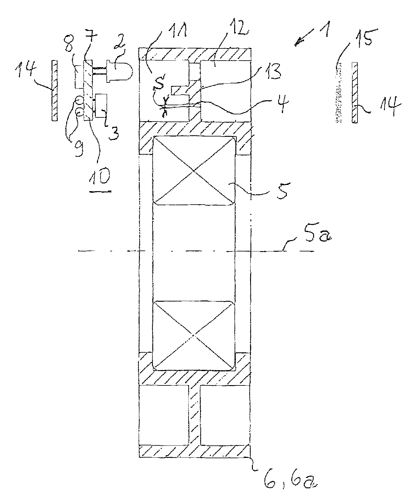
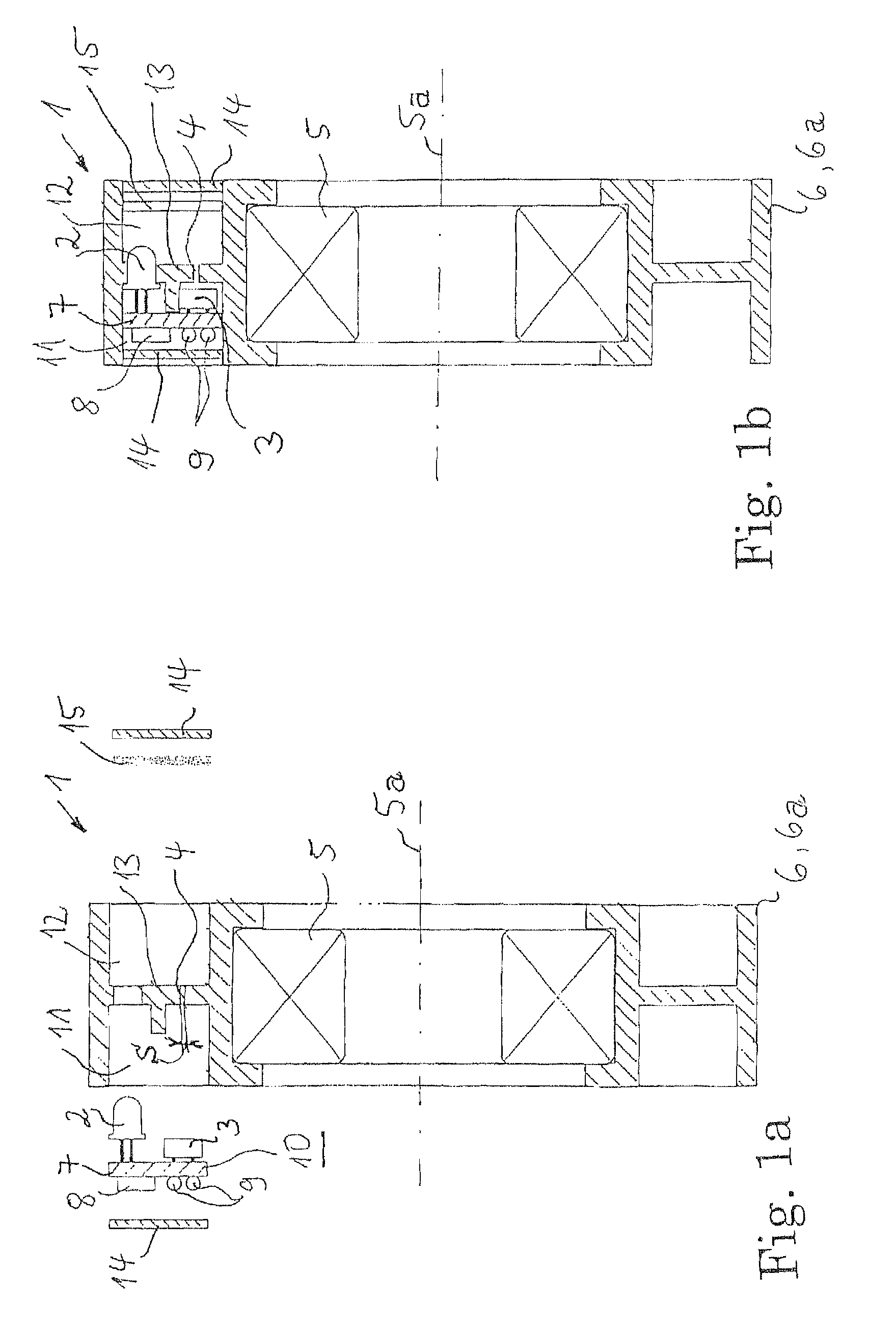
[0019]Referring now to the preferred embodiment of a measuring device for detecting stresses of a bearing arrangement according to the invention is disclosed. FIG. 1a shows the measuring device 1 before final assembly, and FIG. 1b shows the measuring device 1 as a finally assembled module. In this case, the bearing arrangement 5 is a radial bearing, for example a roller or sliding bearing. The measurement device 1 has at least one light source 2, at least one light sensor 3 and at least one light passage 4. The light passage 4 is formed, in a manner which is spatially separated from the bearing arrangement 5, in an at least partially elastically yielding the form of a supporting ring 6a. The radial bearing is held in the supporting ring 6a. The supporting ring 6a is a composite part together with, for example, an outer ring of a rotary bearing. The outer ring (which is not shown in further detail) is encapsulated by injection molding in order to manufacture the composite with the pl...


PUM

PropertyMeasurementUnit
stressaaaaaaaaaa
elastic deformationaaaaaaaaaa
flexibilityaaaaaaaaaa

Abstract

A measuring device for detecting stresses of a bearing arrangement. The stresses are measured based on elastic changes in shape. The inventive measuring device includes a light source, which is directed onto a light passage, and a light sensor. The dimensions of a portion of the light that penetrates the light passage and impinges the light sensor can be modified by elastically changing the shape of the light passage.

Description

FIELD OF THE INVENTION[0001]The invention relates to a measuring device for detecting stresses of a bearing arrangement, it being possible for the stresses to be measured using elastic shape changes.BACKGROUND OF THE INVENTION[0002]A measuring device of this type is described in DE 26 42 044 B1. Static and dynamic stresses of a roller bearing are determined in an elaborate form by means of strain gages. One characteristic variable for the determination of the stress of the bearing is the elastic deformation of the bearing itself. The deformation of a bearing ring with rolling contact under loads is, as a rule, detected by the strain gages. For this purpose, the strain gages are fastened directly to the stressed bearing ring. This sensor system needs installation space on the bearing and is to be protected against environmental influences. Arrangements of this type are therefore complicated as a rule.SUMMARY OF THE INVENTION[0003]It is therefore the object of the invention to provide...

Claims


Application Information

Patent Timeline
Patent Type & Authority Patents(United States)
IPC IPC(8): G01L1/24G01B11/02G01L5/12
CPCG01B11/16G01L5/0009F16C19/522F16C35/042
Inventor GLUECK, STEFAN
Owner SCHAEFFLER TECH AG & CO KG
Why Eureka
Try Eureka