Centrifugal magnetic clutch

a centrifugal and magnetic clutch technology, applied in the direction of magnetically actuated clutches, mechanical actuated clutches, electrostatic holding devices, etc., can solve the problems of limiting the operational life of the clutch, affecting the operation life, and contaminating the bearings, so as to increase the torque transmitted by the motor to the pump

Inactive Publication Date: 2009-05-05
INT BUSINESS MASCH CORP
View PDF12 Cites 50 Cited by
  • Summary
  • Abstract
  • Description
  • Claims
  • Application Information

AI Technical Summary

Problems solved by technology

This slippage of the frictional members creates wear that limits the operational life of the clutch.
Additionally, the wear caused debris that can contaminate bearings and effect the operational life of the bearings as well.
One example is in the pumping of cooling liquids in computers where the immersion of bearings can result in the need for frequent maintenance.
This is due to the fact that SBLDC motors posses very little starting torque.
However, the magnetic centrifugal clutch of '587 prohibits the fluidic isolation of the input shaft from the output shaft.
For pump applications this is problematic since bearings and seals are common sources of leaks.

Method used


Image

  • Centrifugal magnetic clutch
  • Centrifugal magnetic clutch
  • Centrifugal magnetic clutch

Examples


Embodiment Construction

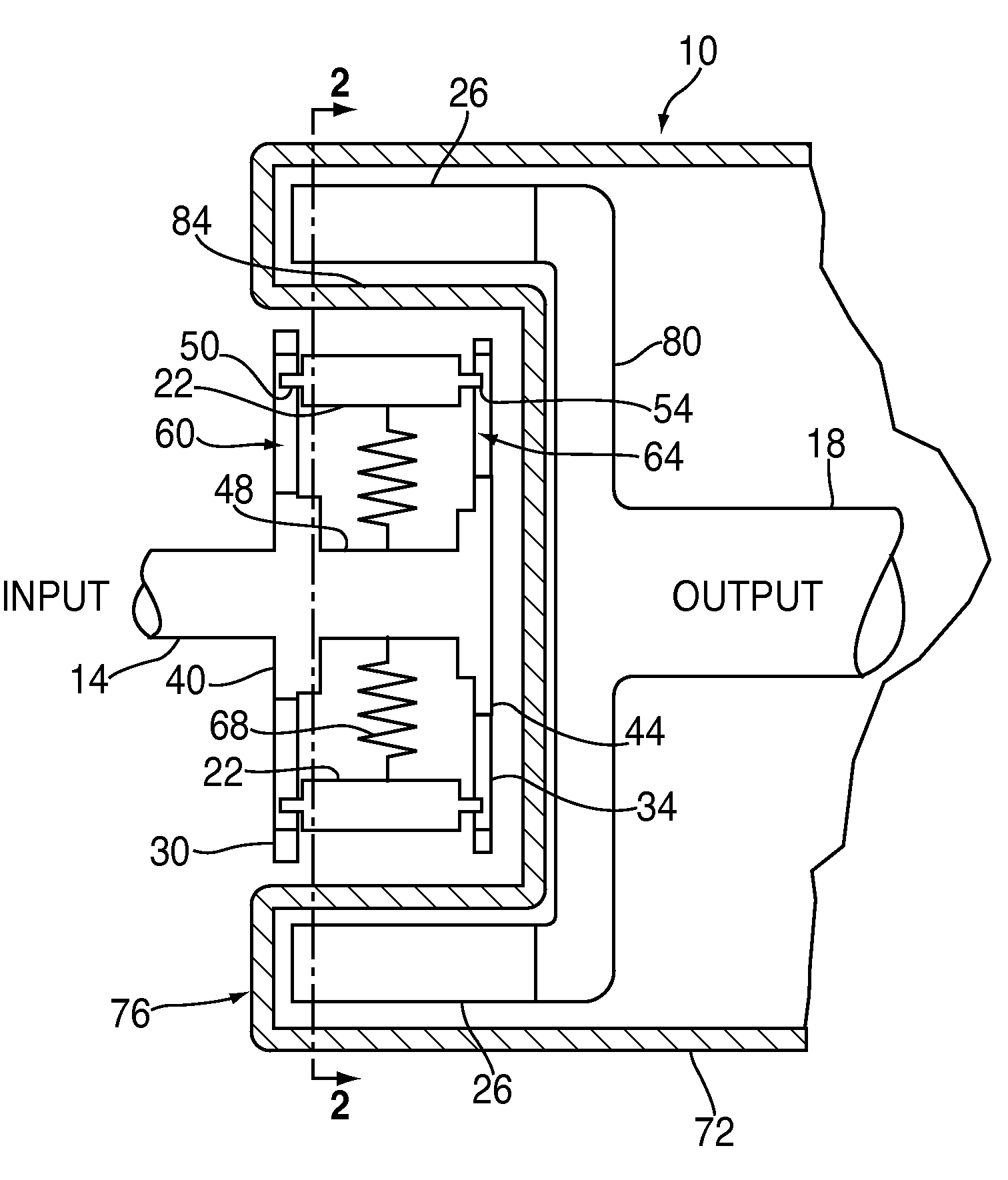
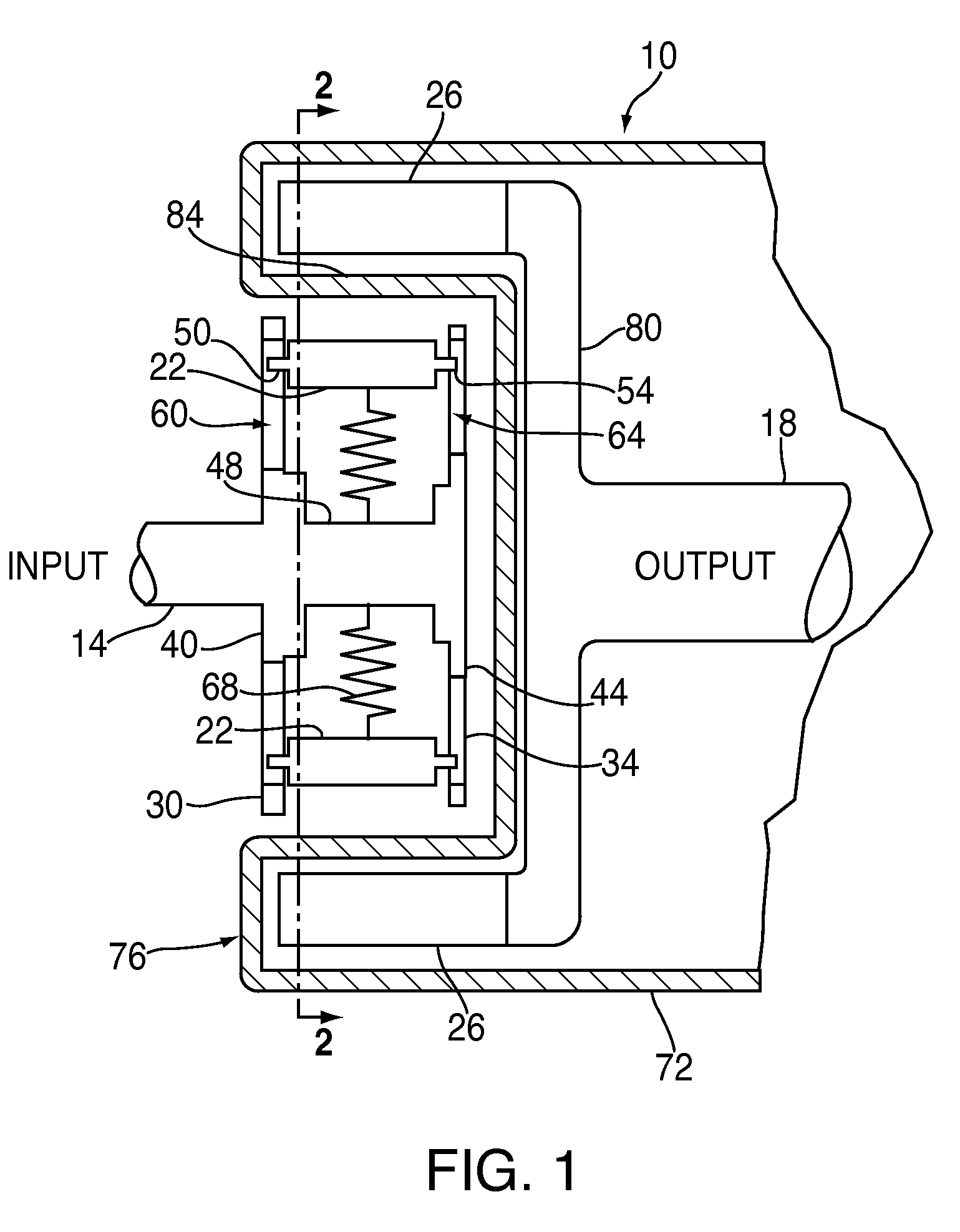
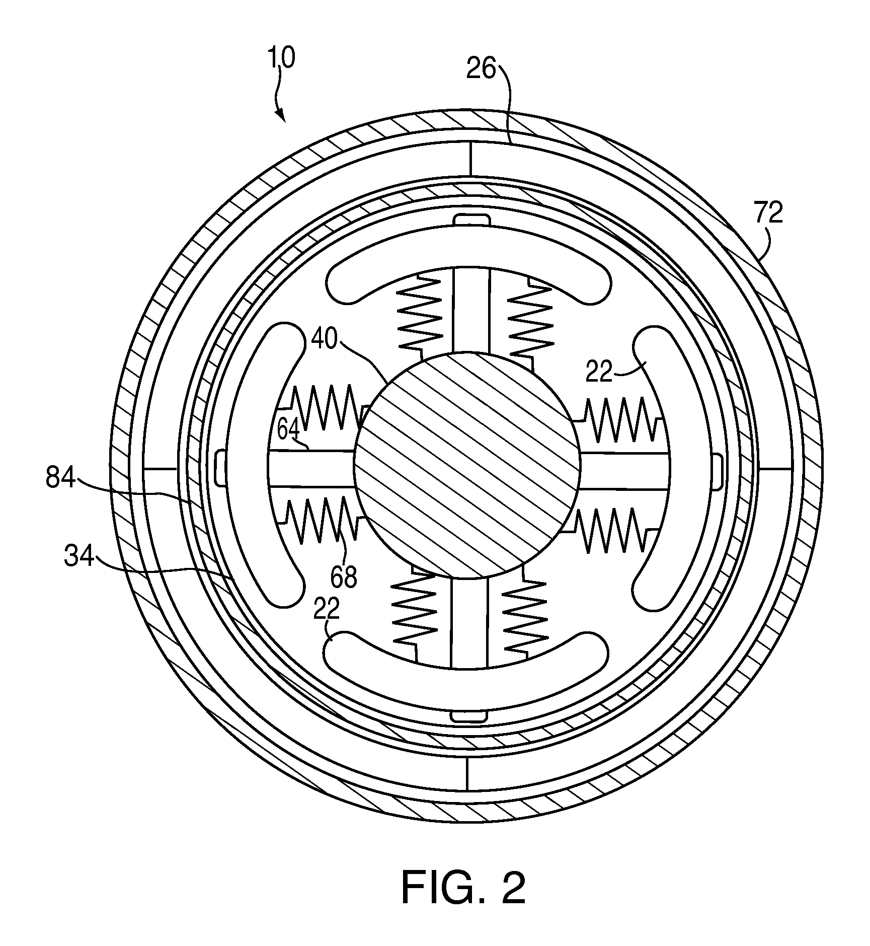
[0019]Turning now to the drawings in greater detail, FIGS. 1 and 2 depict a centrifugal magnetic clutch generally at 10. The clutch 10 transmits a torque from an input shaft 14, driven by a motor (not shown), to an output shaft 18, which drives a pump (not shown). The torque is transmitted through a coupling of magnetic forces between a plurality of input magnets 22, rotationally fixed to the input shaft 14, and a plurality of output magnets 26, rotationally fixed to the output shaft 18. The strength of the magnetic forces is proportional to a distance separating the input magnets 22 from the output magnets 26. This distance separating the input magnets 22 from the output magnets 26 is variable and control of the separating distance will be described now in greater detail.

[0020]The input magnets 22 are radially slidably engaged with a first flange 30 and a second flange 34 that extend radially from a first hub 40 and a second hub 44 respectively. The first hub 40 and the second hub ...


PUM


Abstract

A centrifugal magnetic clutch device includes, an input shaft and, a plurality of input magnets that are rotatable about an axis of the input shaft, and are radially movable relative to the input shaft axis, and are rotationally fixed to the input shaft. The device further includes, a plurality of output magnets rotatable about the input shaft axis and in axial alignment with the plurality of input magnets, and an output shaft rotationally fixed to the plurality of output magnets. The device further includes, a housing for fluidically sealing the plurality of output magnets and the output shaft relative to the plurality of input magnets and the input shaft.

Description

TRADEMARKS[0001]IBM® is a registered trademark of International Business Machines Corporation, Armonk, N.Y., U.S.A. Other names used herein may be registered trademarks, trademarks or product names of International Business Machines Corporation or other companies.BACKGROUND OF THE INVENTION[0002]1. Field of the Invention[0003]This invention relates to centrifugal couplers and particularly to centrifugal clutches that use magnets to transfer the torque between an input shaft and an output shaft.[0004]2. Description of Background[0005]Centrifugal frictional clutches have been used for many years. In general torque of an input shaft is transmitted to an output shaft through the centrifugal clutch. The torque transmitted from the input to the output shaft is a function of the rotational speed of the input shaft, such that the torque transmitted increases as the speed increases. Centrifugal clutches, therefore, by design have slippage of frictionally engaged members as the speed of the o...

Claims


Application Information

Patent Timeline
Patent Type & Authority Patents(United States)
IPC IPC(8): H02K49/00
CPCF16D27/01H02K49/106F16D43/04Y10T464/30
Inventor CRUZ, ETHAN E.TRIFILO, TIMOTHY M.
Owner INT BUSINESS MASCH CORP
Why Eureka
Try Eureka