Electromagnetic clutch assembly having solenoid type operator

a technology of solenoid and clutch assembly, which is applied in the direction of magnetically actuated clutches, mechanical actuated clutches, transportation and packaging, etc., can solve the problems of power consumption and engineering attention, and achieve the effects of reducing power consumption, improving control, and reducing power consumption

Inactive Publication Date: 2005-06-14
BORGWARNER INC
View PDF14 Cites 35 Cited by
  • Summary
  • Abstract
  • Description
  • Claims
  • Application Information

AI Technical Summary

Benefits of technology

[0005]An electromagnetic clutch assembly having a solenoid activated ball ramp operator provides reduced power consumption and improved control. The electromagnetic clutch assembly includes a primary or pilot friction clutch pack and a secondary or main friction clutch pack. An annular coil and housing cooperates with an annular operator or plunger. When the coil is energized, the annular plunger translates and compresses the primary or pilot friction clutch pack. Activation of the pilot clutch pack retards motion of one of the members of the ball ramp actuator which, in turn, compresses a secondary or main friction clutch pack disposed across the input and output members, thereby transferring torque. The friction clutch packs are preferably wet, i.e., are contained within a sealed housing containing clutch fluid. The clutch assembly of the present invention exhibits reduced power consumption and improved linearity of operation.
[0009]It is a still further object of the present invention to provide an electromagnetic clutch having a solenoid type operator and ball ramp actuator which exhibits reduced power consumption and improved linearity of operation.

Problems solved by technology

One of the design and operational characteristics of electromagnetic clutches which receives significant engineering attention is power consumption.

Method used


Image

  • Electromagnetic clutch assembly having solenoid type operator
  • Electromagnetic clutch assembly having solenoid type operator
  • Electromagnetic clutch assembly having solenoid type operator

Examples


Embodiment Construction

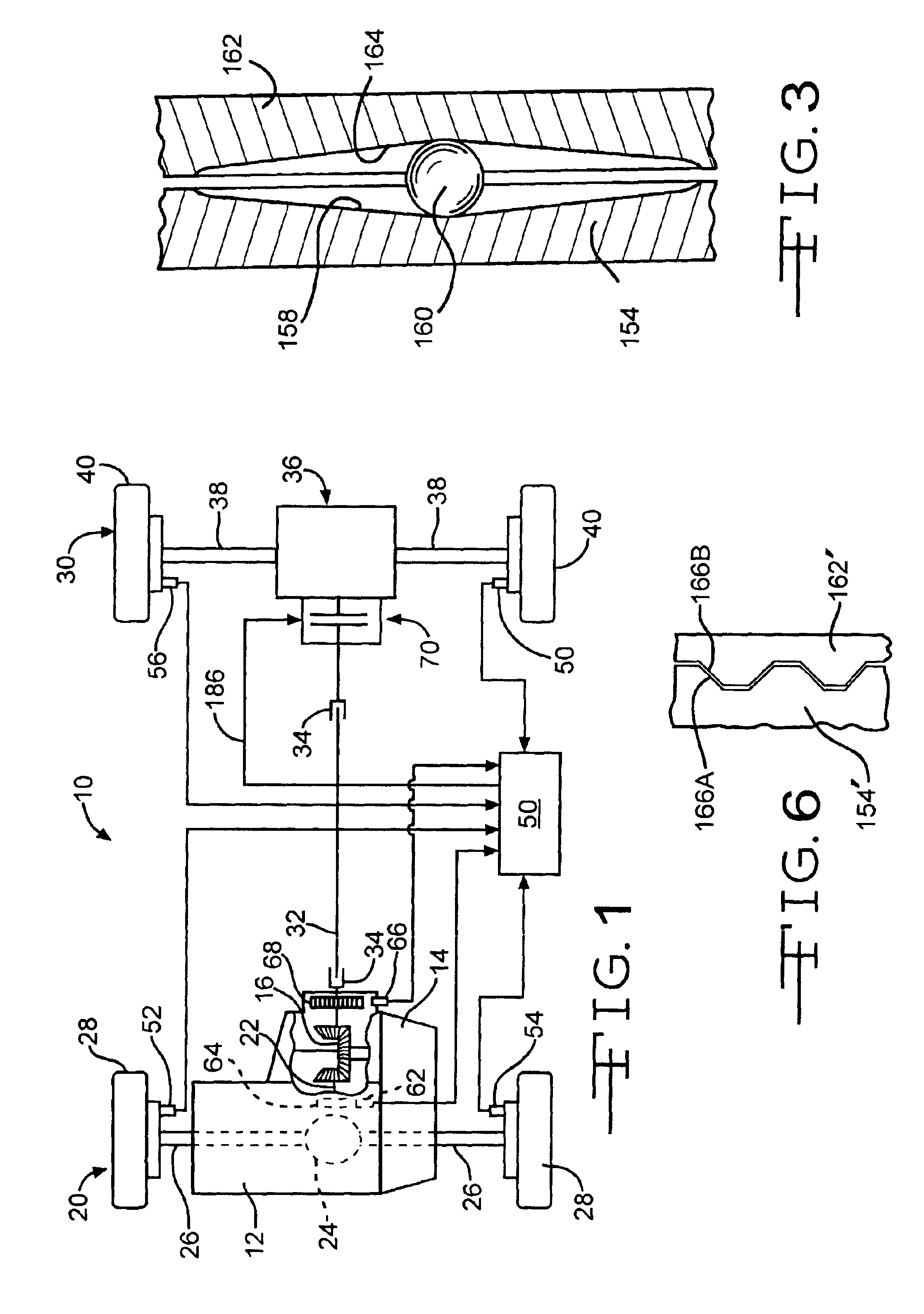
[0018]Referring now to FIG. 1, a four-wheel vehicle drive train incorporating the present invention is diagrammatically illustrated and designated by the reference number 10. The four-wheel vehicle drive train 10 includes a prime mover 12 which is coupled to and directly drives a transaxle 14. The output of the transaxle 14 drives a beveled or spiral beveled gear set 16 which provides motive power to a primary or front drive line 20 comprising a front or primary propshaft 22, a front or primary differential 24, a pair of live front axles 26 and a respective pair of front or primary tire and wheel assemblies 28. It should be appreciated that the front or primary differential 24 is conventional.

[0019]The beveled or spiral beveled gear set 16 also provides motive power to a secondary or rear drive line 30 comprising a secondary propshaft 32 having appropriate universal joints 34, a rear or secondary differential assembly 36, a pair of live secondary or rear axles 38 and a respective pa...


PUM


Abstract

An electromagnetic clutch assembly having a solenoid activated ball ramp operator provides reduced power consumption and improved control. The electromagnetic clutch assembly includes a primary or pilot friction clutch pack and a secondary or main friction clutch pack. An annular solenoid coil cooperates with an annular operator or plunger. When the coil is energized, the annular plunger translates and compresses the primary or pilot friction clutch pack. Activation of the pilot clutch pack retards motion of one of the members of the ball ramp operator which, in turn, compresses a secondary or main friction clutch pack disposed across the input and output members.

Description

BACKGROUND OF THE INVENTION[0001]The invention relates generally to electromagnetic clutches and more specifically to an electromagnetic clutch having a solenoid activated ball ramp operator.[0002]Clutches which are activated or energized by electromagnetic coils are extraordinarily common components in rotary power transmission systems, both in stationary applications and in motor vehicles. Such electromagnetic clutches may be broadly characterized by whether they provide on-off energy transfer or modulating energy transfer. In the case of the former, dog clutches which may include auxiliary synchronizing devices are utilized whereas in the latter, friction clutch packs having a plurality of interleaved friction plates or discs are utilized. In either case, an electromagnetic operator which translates or compresses components of the clutch upon energization activates the clutch and upon deenergization deactivates or relaxes the clutch.[0003]One of the design and operational charact...

Claims


Application Information

Patent Timeline
Patent Type & Authority Patents(United States)
IPC IPC(8): F16D27/115F16D27/10B60K17/344F16D13/52
CPCF16D27/115F16D27/004B60K17/344
Inventor KOWALSKY, CHRISTOPHER J.PRITCHARD, LARRY A.KAPPLER, BRIAN
Owner BORGWARNER INC
Why Eureka
Try Eureka