Electromagnetic clutch

a technology of electromagnetic clutch and rotor, which is applied in the direction of fluid clutch, clutch, non-mechanical actuated clutch, etc., can solve the problems of electromagnetic clutch inoperative, rotor rotating by slipping, and abnormal slippage between rotor and armatur

Active Publication Date: 2009-12-24
OGURA CLUTCH CO LTD
View PDF4 Cites 35 Cited by
  • Summary
  • Abstract
  • Description
  • Claims
  • Application Information

AI Technical Summary

Benefits of technology

[0018]It is an object of the present invention to provide a self-hold electromagnetic clutch in which belt burnout, bearing seizure, and the like caused by frictional heat upon slip rotation of a rotor can be prevented.

Problems solved by technology

If, however, the rotating shaft of the driven device is locked (stopped) by an overload, or oil is externally attached between the frictional surfaces of the rotor and armature, abnormal slippage occurs between the rotor and armature, and the rotor rotates by slipping.
Then, a belt that transmits the rotation of the driven device to the rotor may be burned, or the grease of the bearing that axially supports the rotor may flow out to seize the bearing, quickly rendering the electromagnetic clutch inoperative.
When the temperature of the input pulley increases abnormally, the heat-shrinkable member of the temperature detector shrinks to cut off an output from the rotation pickup device.
This cuts off energization to an excitation coil and causes the input pulley to idle.
In this case, however, the rotation pickup device must be mounted in the stationary housing of the driven device such that it opposes the pulley.
Accordingly, an installation space is required, and the assembly operation becomes cumbersome.
Also, the number of constituent components of the electromagnetic clutch increases, leading to a high product cost.
Also, the number of components increases, so the product cost increases.

Method used


Image

  • Electromagnetic clutch
  • Electromagnetic clutch
  • Electromagnetic clutch

Examples


Embodiment Construction

[0030]The present invention will be described in detail hereinafter based on preferred embodiments shown in the accompanying drawings.

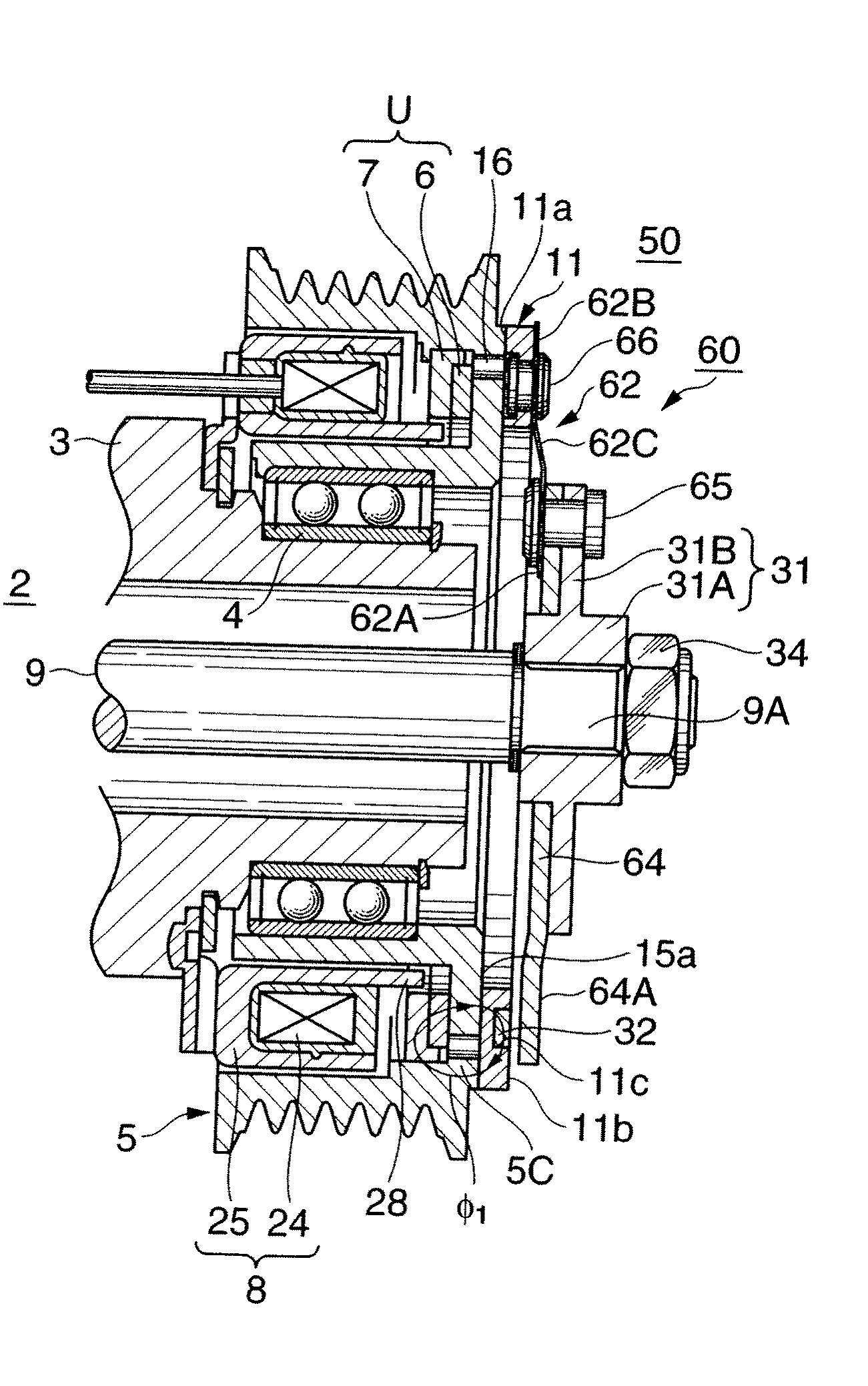
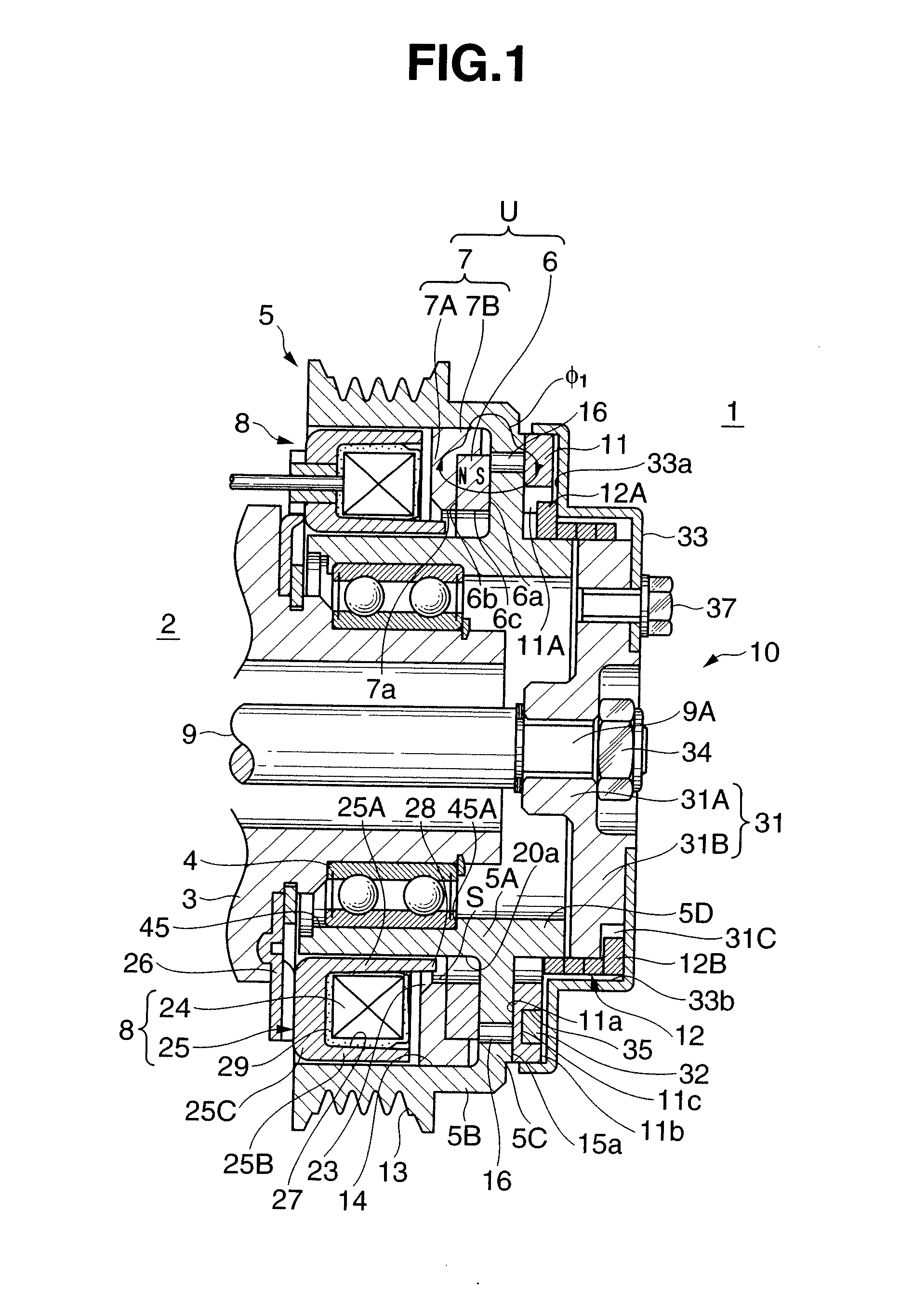
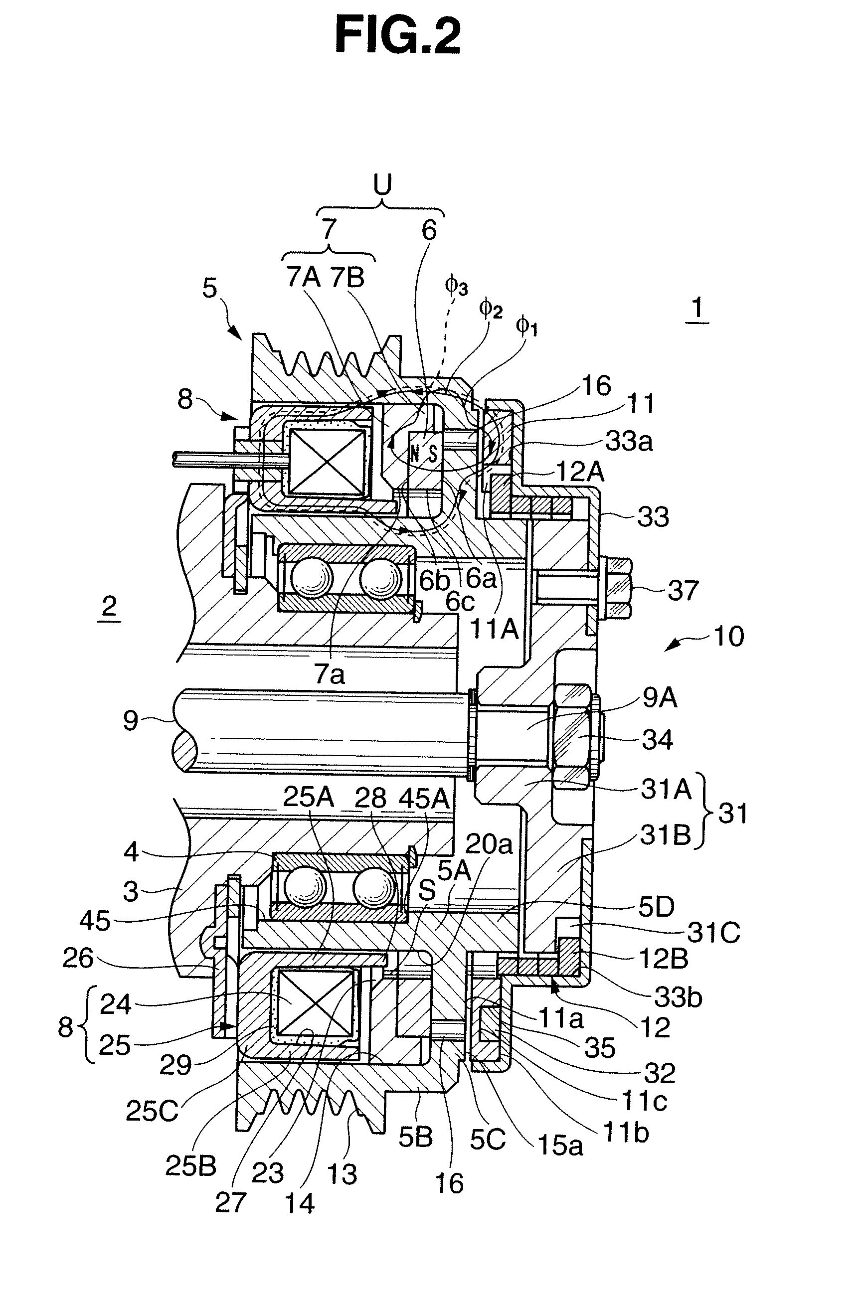
[0031]FIGS. 1 to 3 show an embodiment in which the present invention is applied to an electromagnetic clutch 1 which transmits and cuts off rotation of an engine (not shown) serving as a driving device to the rotating shaft of a water pump as a driven device.

[0032]The electromagnetic clutch 1 forms a self-hold electromagnetic spring clutch which transmits power by using both a permanent magnet and coil spring, and roughly includes a rotor 5 rotatably disposed in a housing 3 of a water pump 2 through a bearing 4, a magnet unit U and excitation coil device 8 incorporated in the rotor 5, and an armature assembly 10 which transmits the rotation of the rotor 5 to a rotating shaft 9 of the water pump 2. The magnet unit U includes a power transmission permanent magnet 6 and magnetic body 7. The armature assembly 10 includes an armature 11, coil spring 12, ar...


PUM


Abstract

An electromagnetic clutch includes a rotor, armature hub, armature, magnetic body and first permanent magnet, field core, excitation coil, and second permanent magnet. The rotor is rotatably disposed in the housing of a driven device. The armature hub is fixed to the rotating shaft of the driven device. The armature is disposed on the armature hub to be movable in an axial direction. The magnetic body is incorporated in the rotor. The first permanent magnet connects the armature to the rotor. The field core is attached to the housing and inserted in the rotor to be in noncontact with it. The excitation coil is disposed in the field core and excited, when cutting off power transmission, to cancel a magnetic force of the first permanent magnet, thus releasing the armature from the first permanent magnet. The second permanent magnet separates the armature from the rotor, when cutting off power transmission, to move the armature toward the armature hub. The first permanent magnet has a Curie temperature lower than the temperature of heat generated by the rotor upon slip rotation.

Description

BACKGROUND OF THE INVENTION[0001]The present invention relates to an electromagnetic clutch which transmits power by utilizing a magnetic force generated by the magnetic flux of a permanent magnet and cuts off power transmission by energizing an excitation coil.[0002]Various types of electromagnetic clutches which transmit power by a magnetic force generated by the magnetic flux of a permanent magnet (to be merely referred to as a magnetic force as well hereinafter) are conventionally proposed (see U.S. Pat. No. 3,263,784, Japanese Utility Model Publication No. 63-011394, and Japanese Patent Laid-Open No. 2007-333109).[0003]A non-excitation actuation type electromagnetic clutch described in U.S. Pat. No. 3,263,784 includes a rotor attached to a rotating shaft, a hub rotatably attached to the rotating shaft through a bearing, an armature attached to the hub, and a permanent magnet and excitation coil which line up on the rotor in the axial direction. The rotor is formed of two member...

Claims


Application Information

Patent Timeline
Patent Type & Authority Applications(United States)
IPC IPC(8): F16D27/112
CPCF16D27/105F16D2027/008F16D2027/007F16D27/112
Inventor KATO, MOTOIKUROSU, YOSHIHIROUSHIRODE, HARUHIKO
Owner OGURA CLUTCH CO LTD
Why Eureka
Try Eureka