
Microwave oscillator tuned with a ferromagnetic thin film

a ferromagnetic thin film and microwave technology, applied in the direction of automatic frequency control, pulse automatic control, electrical equipment, etc., can solve the problems of very limited literature on parametric excitation and the choice of tunable resonance phenomena benefiting from a very large quality factor q in the microwave frequency rang

Inactive Publication Date: 2009-05-05
COMMISSARIAT A LENERGIE ATOMIQUE ET AUX ENERGIES ALTERNATIVES
View PDF7 Cites 40 Cited by
  • Summary
  • Abstract
  • Description
  • Claims
  • Application Information

AI Technical Summary

Benefits of technology

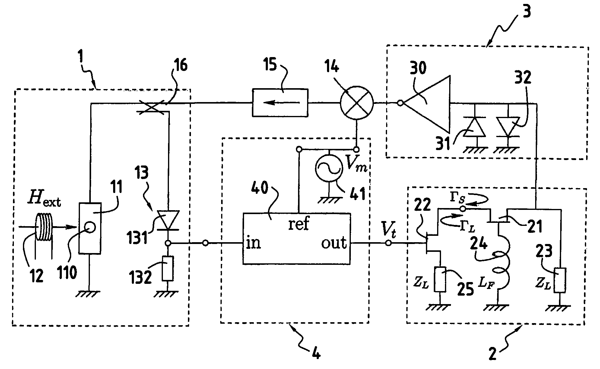
The present invention aims to improve the performance of microwave oscillators that use a ferromagnetic thin film resonator tuned with a microwave excitation. The invention provides a YIG tuned oscillator with high Q and a compact design that can be built into a microwave integrated circuit. The use of parametric resonance as the tuning element allows for the observation of standing spin-waves resonances with Qs that are more than an order of magnitude larger than the highest Q reported previously. The invention also utilizes the low inductance coil described in U.S. Pat. No. 4,887,052 for speed or consumption optimization. The invention can be used for sensitive magnetic field detection at large bias. The overall positive feedback loop includes an amplitude stabilized amplifier and an oscillator for superimposing a small ac-modulation. The ferromagnetic thin film resonance plate is advantageously a YIG crystal which is preferably disk-shaped. The microwave integrated circuit may comprise a half-wavelength strip-line resonator and the active element for oscillation may comprise a fast transistor such as a GaAs FET.

Problems solved by technology

The choice of tunable resonance phenomena benefiting from very large quality factor Q is very limited in the microwave frequency range.
The literature on parametric excitations is very limited.

Method used


Image

  • Microwave oscillator tuned with a ferromagnetic thin film
  • Microwave oscillator tuned with a ferromagnetic thin film
  • Microwave oscillator tuned with a ferromagnetic thin film

Examples


Embodiment Construction

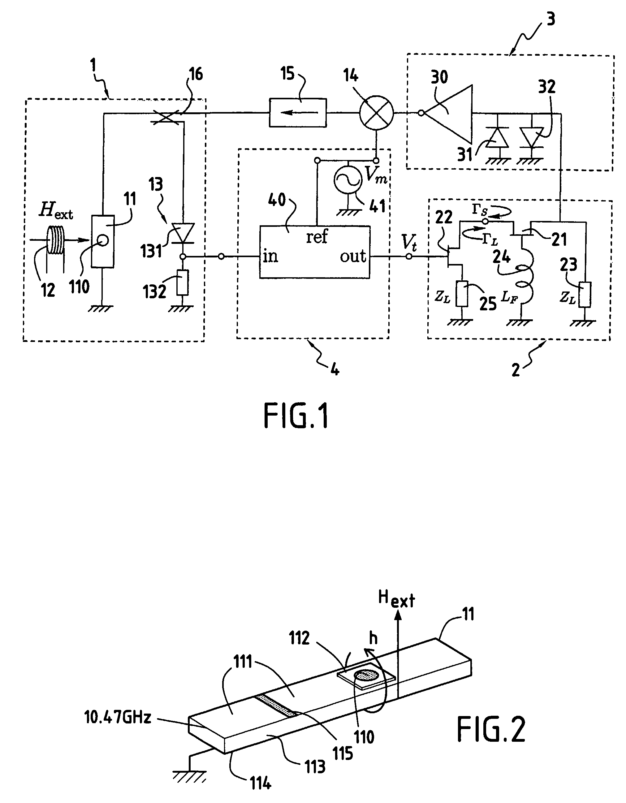
[0034]FIG. 1 is a block diagram of an example of a tuned oscillator according to the present invention. This oscillator has been divided into four modules for conveniences: a microwave integrated circuit containing a YIG resonator 110 and its associated detector 13, a tuned oscillator 2, an amplitude stabilized amplifier 3 and a load feedback 4 to the tuned oscillator.

[0035]The tuned oscillator 2 comprises a fast transistor 21 like a GaAs FET. The drain of the transistor 21 is connected to an impedance matching load (ZL) 23. The gate is grounded through a feedback reactance (L) 24. The source of transistor 21 is connected to another transistor 22 that varies the load (ZL) 25 depending on the frequency of the auto-oscillation of the tuned oscillator 2. This is achieved by monitoring the properties of a YIG sample 110 placed on a microwave-integrated circuit (MIC) 11 and excited by the oscillator output 16. Overall positive feedback is used to cause a sustained oscillation to build up...


PUM


Abstract

A microwave tuned oscillator utilizing a ferromagnetic thin film resonator comprises: a) a microwave resonator (1) comprising a ferromagnetic thin film resonance plate (110) such as a disc-shaped YIG crystal placed on a microwave integrated circuit (11), such as a half-wavelength strip-line resonator, b) bias magnetic field means (12) for applying a bias magnetic field perpendicular to the ferromagnetic thin film resonance plate (110), c) an active element for oscillation (21), a reactive feedback element (24) and a load (23, 25) controlled by the microwave properties of the ferromagnetic thin film resonance plate (110) through a load feedback loop (4), and d) an overall positive feedback loop (3, 14, 15) connected between the active element for oscillation (21) and the microwave resonator (1) to cause a sustained oscillation to build up at one of parametrically excited resonances of the ferromagnetic thin film resonance plate (110).

Description

[0001]This application is a §371 national phase filing of PCT / EP2004 / 010987 filed Sep. 15, 2004.BACKGROUND OF THE INVENTION[0002]1. Field of the Invention[0003]The present invention concerns a micro-wave tuned oscillator with ultra-low phase noise. Application includes counters, timers, receivers, or waveform generators and a host of other devices that can be found for example in communication devices, modern computers or their peripherals to name a few.[0004]2. Description of the Related Art[0005]The choice of tunable resonance phenomena benefiting from very large quality factor Q is very limited in the microwave frequency range. Ferromagnetic resonance has been found the best tuning element for microwave oscillators. There are several reasons which explain this preference: one benefits both from the large electronic magnetic moment (as opposed for example to nuclear magnetic resonance, where the Bohr magnetron is 3 order of magnitude weaker) and a saturated magnetization at low fi...

Claims


Application Information

Patent Timeline
Patent Type & Authority Patents(United States)
IPC IPC(8): H03L7/099
CPCH03B5/1888
Inventor NALETOV, VLADIMIRKLEIN, OLIVIER
Owner COMMISSARIAT A LENERGIE ATOMIQUE ET AUX ENERGIES ALTERNATIVES
Learn More