Transmitter

a transmitter and receiver technology, applied in the field of transmitters, can solve the problems of increasing power leakage to outside the band, increasing the loss of peak power limiting effect, and increasing the frequency spectrum, and achieve the effect of suppressing the peak level of the transmit signal

Inactive Publication Date: 2009-05-05
KOKUSA ELECTRIC CO LTD
View PDF8 Cites 2 Cited by
  • Summary
  • Abstract
  • Description
  • Claims
  • Application Information

AI Technical Summary

Benefits of technology

[0009]The present invention was accomplished in light of the foregoing circumstances and has as an object to provide a transmitter, that, when transmitting a transmit signal, can effectively suppresses the peak level of the transmit signal.
[0012]Therefore, the transmit signal peak level can be effectively suppressed by, as explained in the foregoing, using the peak reduction signal having the prescribed level and prescribed phase based on the transmit signal to suppress the level of the transmit signal.
[0023]Therefore, the peak of the transmit signal and the level in the vicinity thereof can be suppressed by using the band-restricted peak reduction signal to suppress the level of the transmit signal, whereby it is possible, for example, to achieve more effective peak level suppression than previously achieved. Specifically, both the effect of peak level suppression and the effect of reduction of power leakage to outside the band can be obtained.
[0041]As explained in the foregoing, at the time of transmitting a transmit signal, the transmitter of the present invention generates a peak reduction signal having a level based on a transmit signal level threshold for determining the peak of the transmit signal and on the transmit signal peak level and has a phase based on the phase of the transmit signal, and subtracts the generated peak reduction signal from the transmit signal, thereby suppressing the level of the transmit signal. As a result, the level of the transmit signal peak can be effectively suppressed.
[0042]Moreover, the transmitter of the present invention subjects the generated peak reduction signal to band restriction and orthogonal modulation and subtracts the peak reduction signal subjected to the band restriction and orthogonal modulation from the transmit signal, thereby suppressing the level of the transmit signal. As a result, it is possible to realize the effects of both peak level suppression and reduction of power leakage to outside the band, thereby achieving effective peak level suppression.

Problems solved by technology

In wireless communication and the like, however, since the frequency band used for communication is limited, a need arises to minimize the expansion of the frequency spectrum caused by the nonlinear distortion of the power and other amplifiers.
However, the conventional configuration has a problem in that it increases power leakage to outside the band more than it lowers the peak level.
This is a problem because the peak power limiting effect is also lost.

Method used


Image

  • Transmitter
  • Transmitter
  • Transmitter

Examples


first embodiment

[0058]A first embodiment of the present invention will be explained.

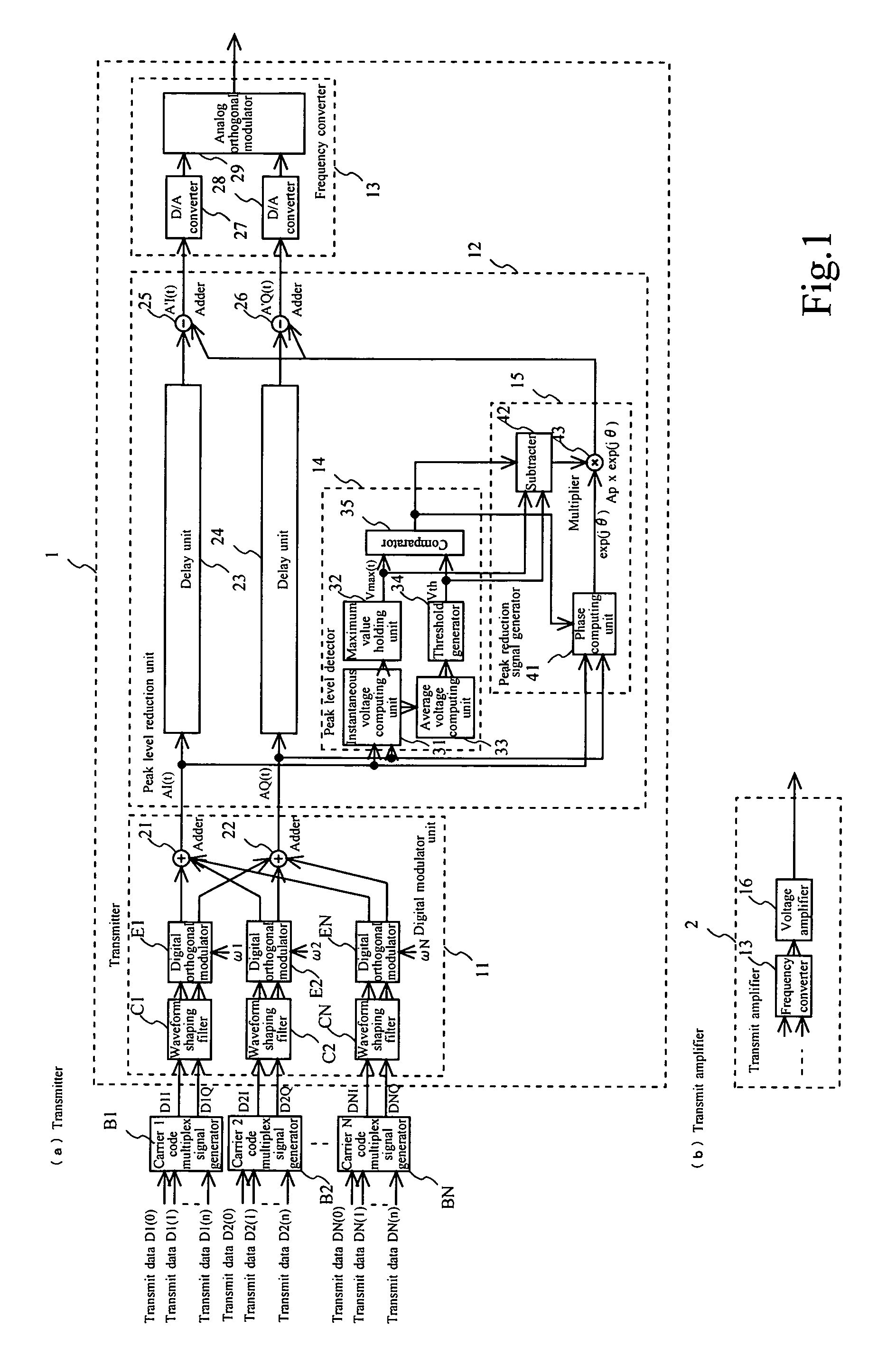
[0059]FIG. 1(a) shows the configuration of the transmitter 1 of this embodiment. B1 to BN in this figure designate code multiplex signal generators associated with N number (N>1) of carriers (carriers 1-N).

[0060]The transmitter 1 of this embodiment is equipped with a digital modulator unit 11, peak level reduction unit 12, and frequency converter 13.

[0061]The digital modulator unit 11 is equipped with N number of waveform shaping filters C1-CN, N number of digital orthogonal modulators E1-EN, an adder (synthesizer) 21 for I component signals (I signals), and an adder (synthesizer) 22 for Q component signals (Q signals).

[0062]The peak level reduction unit 12 is equipped with a delay unit 23 and subtracter 25 associated with the I signal, a delay unit 24 and subtracter 26 associated with the Q signal, a peak level detector 14, and a peak reduction signal generator 15.

[0063]The peak level detector 14 is equipped with a...

second embodiment

[0101]A second embodiment of the present invention will now be explained.

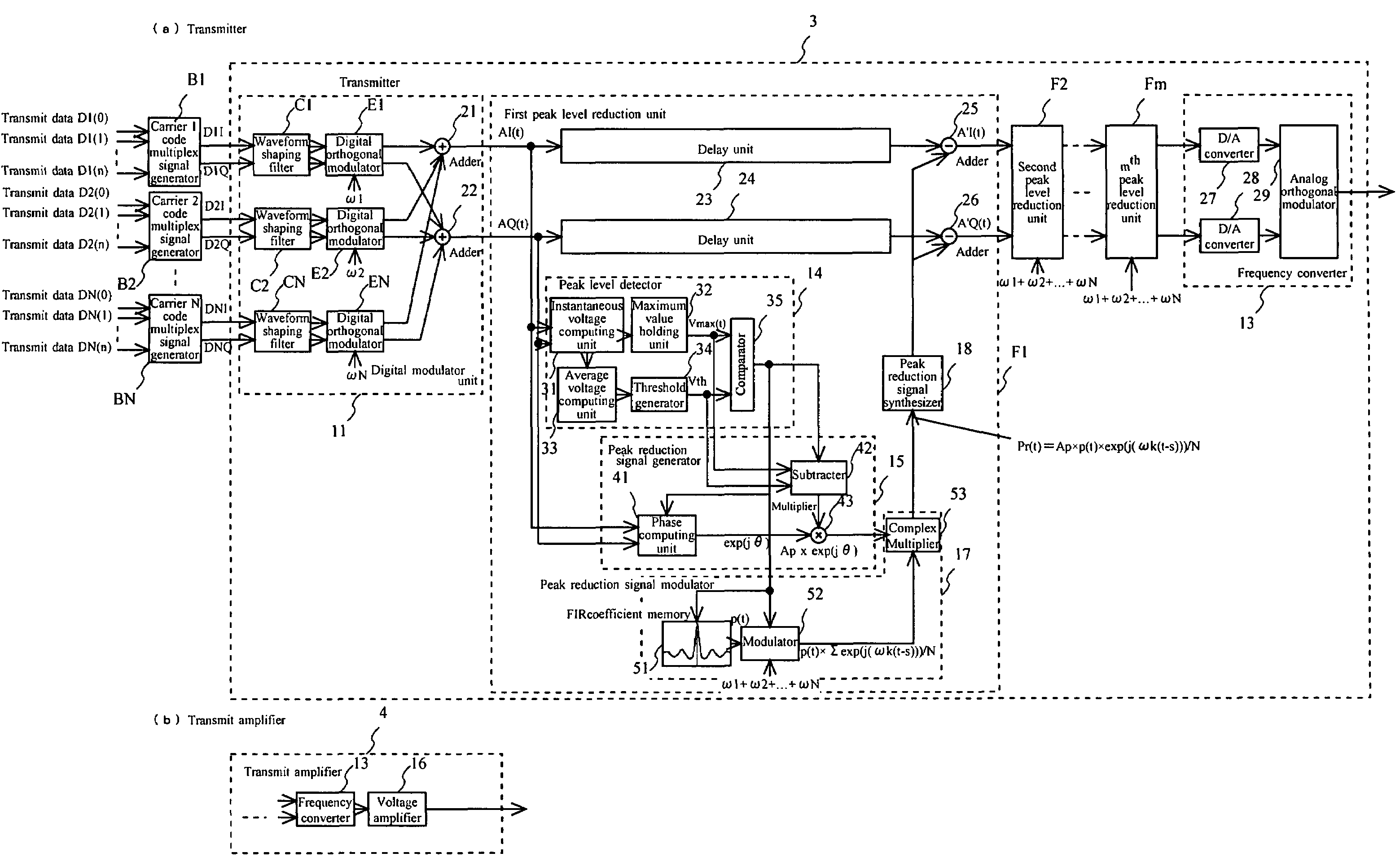
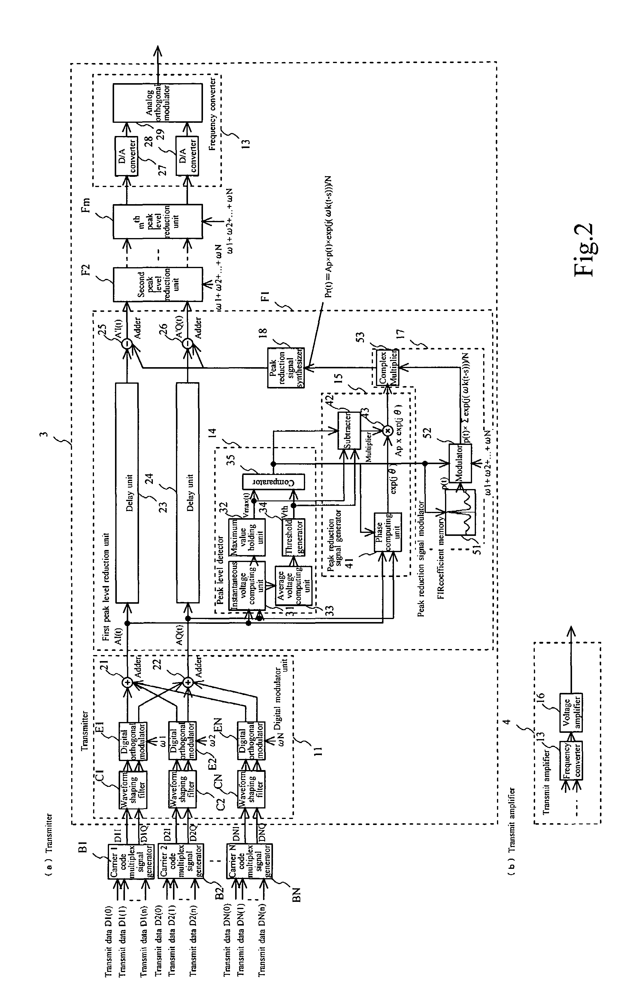
[0102]FIG. 2(a) shows the configuration of a transmitter 3 of this embodiment. It also shows code multiplex signal generators B1-BN associated with N number (N>1) of carriers (carriers 1-N).

[0103]The transmitter 3 is equipped with the digital modulator unit 11, m number of peak level reduction units F1-Fm (m>1), and the frequency converter 13. The peak level reduction units F1-Fm are identical in configuration and operation.

[0104]The transmitter 3 of this embodiment is, in its general configuration, different from the transmitter 1 of FIG. 1(a) in the point that it is equipped with the plurality of peak level reduction units F1-Fm connected in series and in the point that each of the peak level reduction units F1-Fm is equipped with a peak reduction signal modulator 17 and a peak reduction signal synthesizer 18.

[0105]In the transmitter 3 of this embodiment, each of the peak level reduction units F1-Fm subjects ...

third embodiment

[0140]A third embodiment of the present invention will now be explained.

[0141]FIG. 5 shows the configuration of a transmitter 5 of this embodiment. It also shows code multiplex signal generators B1-BN associated with N number (N>1) of carriers (carriers 1-N). It should be noted that application to a transmit amplifier is also possible, although no drawing or explanation relating to such application is shown.

[0142]The transmitter 5 of this embodiment has the general configuration obtained by, in a configuration such as that of the transmitter 1 shown in FIG. 1(a), eliminating the peak level reduction unit 12, connecting a digital modulator unit 11a and the frequency converter 13, and installing peak level reduction units H1-HN having the same configuration as the peak level reduction unit 12 at the stage before the waveform shaping filters C1-CN.

[0143]In the transmitter 5 of this embodiment, peak level reduction processing is conducted in the digital modulator unit 11a, separately, f...


PUM


Abstract

A transmitter, that effectively suppresses a peak level of transmit signals, equipped with a peak reduction signal generating means that generates a peak reduction signal. A level of the peak reduction signal is based on a transmit signal level threshold for determining a peak of the transmit signal, and is based on a transmit signal peak level. Further, a phase of the peak reduction signal is based on the phase of the transmit signal. The transmitter is also equipped with a peak reduction signal processing means that subjects the peak reduction signal to band restriction and orthogonal modulation, and is equipped with a transmit signal level suppressing means that subtracts the peak reduction signal subjected to band restriction and orthogonal modulation from the transmit signal.

Description

BACKGROUND OF THE INVENTION[0001]1. Field of the Invention[0002]This invention relates to a transmitter for transmitting transmit signals. More specifically, this invention relates to a transmitter that effectively suppresses the peak level of transmit signals.[0003]2. Description of the Related Art[0004]In a wireless communication system transmitter that utilizes CDMA (Code Division Multiple Access), for example, the peak level of the transmit signals is suppressed.[0005]An example that can be cited explains that in a carrier synthesizing transmission circuit equipped with a limiter circuit, defining the ratio of the instantaneous power of the signal obtained by multiplexing all carriers to the average power thereof as the instantaneous peak factor, comparing the instantaneous peak factor with a reference value to determine a limit coefficient suitable for the required degree of clipping, and using the limit coefficient to apply required clipping to the instantaneous powers transmi...

Claims


Application Information

Patent Timeline
Patent Type & Authority Patents(United States)
IPC IPC(8): H04K1/02H04B1/04H04J13/00H04L27/26H04L27/36
CPCH04B1/707H04B2201/70706H04L27/2614
Inventor HASEGAWA, NORIOMIYATANI, TETSUHIKOAKAIWA, YOSHIHIKO
Owner KOKUSA ELECTRIC CO LTD
Why Eureka
Try Eureka