Golf club head

a golf club head and golf club technology, applied in golf clubs, golf courses, sport apparatus, etc., can solve the problems of adhesive resin viscosity decline and adhesive resin flow out, and achieve the effect of improving strength and durability, enhancing bonding strength, and improving durability

Inactive Publication Date: 2009-05-12
BRIDGESTONE SPORTS
View PDF94 Cites 307 Cited by
  • Summary
  • Abstract
  • Description
  • Claims
  • Application Information

AI Technical Summary

Benefits of technology

[0009]In order to solve this problem, the invention provides a golf club head, which makes it possible to easily join and integrate the metal crown portion and the fiber reinforced resin.
[0011]According to this structure, the fiber-reinforced-plastic body is superposed on the upper surface of the front edge portion of the crown portion made of the metal, and the recess portion is formed in the front edge portion of the crown portion. For this reason, when the adhesive resin is interposed between the metal crown portion and the prepreg sheet used to form the fiber-reinforced-plastic body, and is subjected to heating and pressurization, the adhesive resin is caught in the recess portion and is prevented from flowing out. Namely, the recess portion functions as an anchor for the adhesive resin.
[0012]As a result, the adhesive resin can be reliably interposed between the metal crown portion and the prepreg sheet, thereby making it possible to join the two members.
[0013]According to the above-described structure, the recess portion also functions as an anchor portion for enhancing the bonding strength between the fiber-reinforced-plastic body and the front edge portion of the crown portion made of the metal, so that the strength and durability of the golf club head improve.
[0018]According to this structure, the bonding strength between the metal crown portion and the fiber-reinforced-plastic body becomes high.
[0022]According to this structure, it is possible to increase the bonding strength between the entire metal crown portion and the fiber-reinforced-plastic body.

Problems solved by technology

For the purpose of this temporary fixing, it is preferable to interpose an adhesive resin between the prepreg sheet and the metal crown portion; however, when heating and pressurization are performed, there is a possibility that the viscosity of this adhesive resin declines and the adhesive resin flows out.

Method used


Image

  • Golf club head
  • Golf club head
  • Golf club head

Examples


Embodiment Construction

[0039]Hereafter, a description will be given of the embodiments of the invention with reference to the drawings.

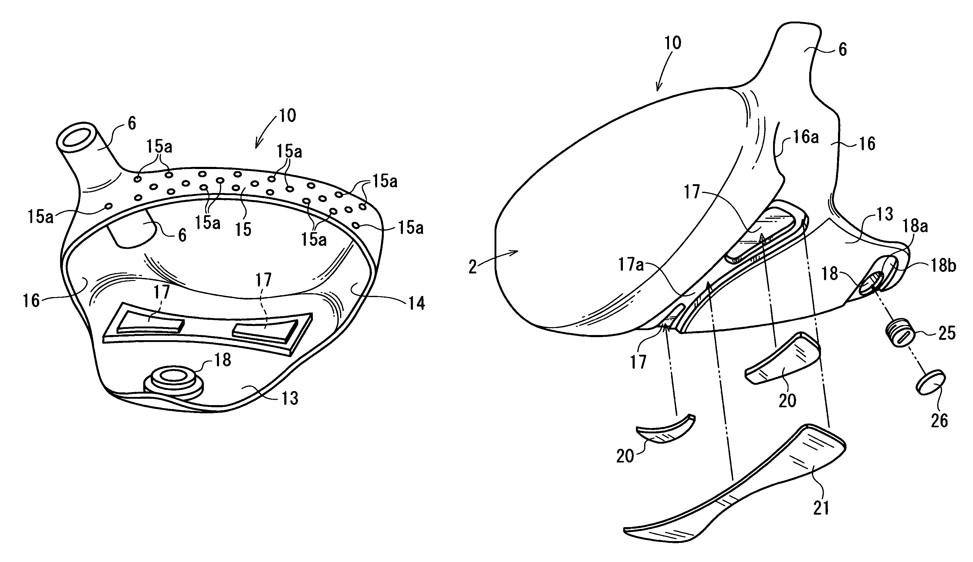
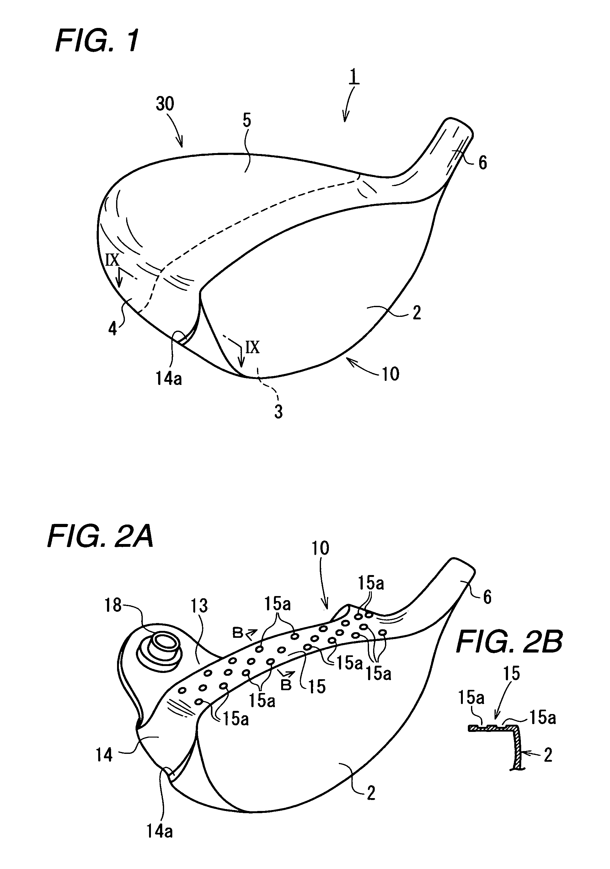
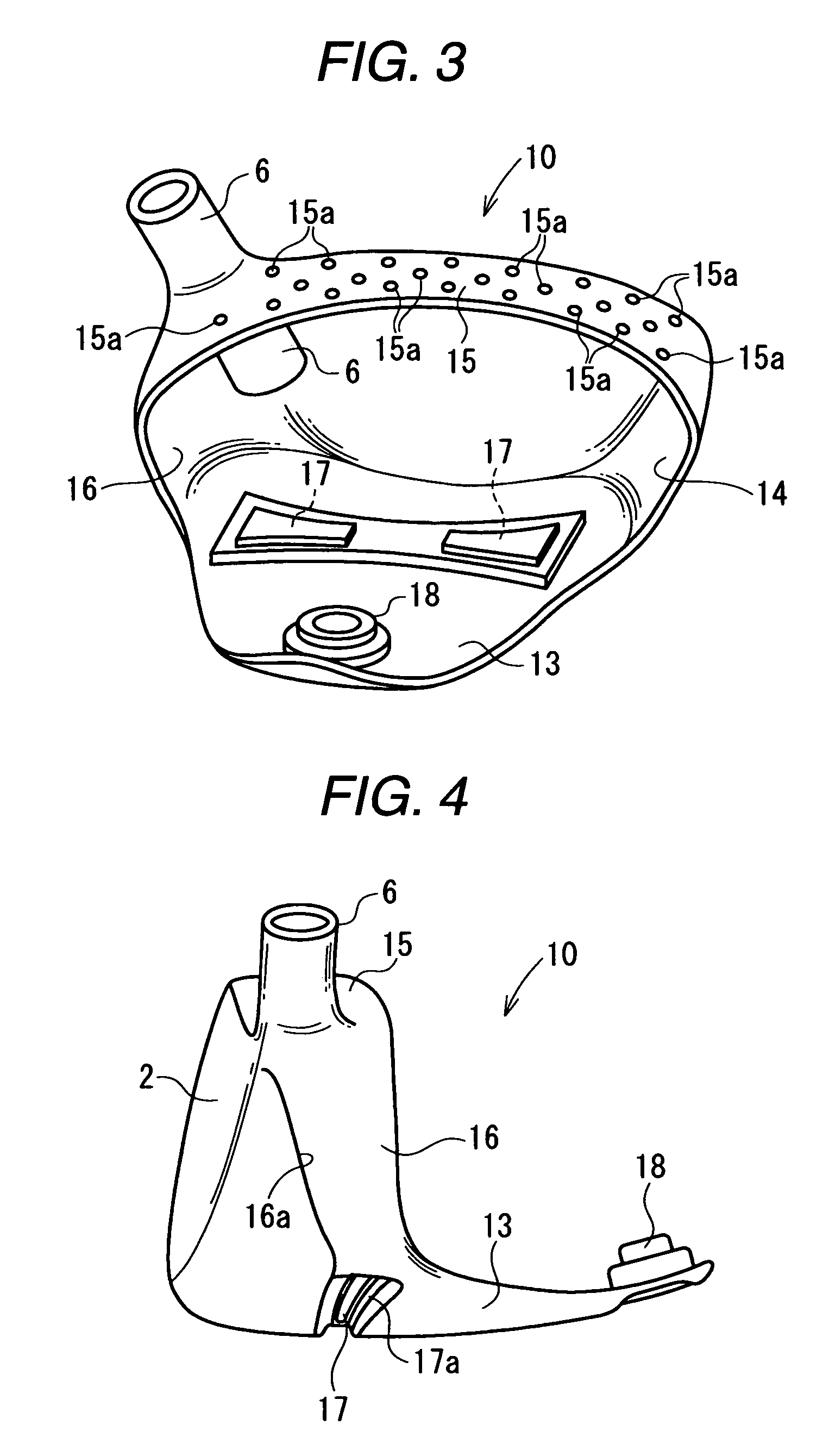
[0040]This golf club head 1 is a hollow wood-type golf club head having a face portion 2, a sole portion 3, a side portion 4, a crown portion 5, and a hosel portion 6.

[0041]The face portion 2 is a surface for hitting a ball, and is formed with grooves (score lines), which are not shown. The sole portion 3 constitutes a bottom portion of the golf club head. The side portion 4 constitutes side surface portions on the toe side, the heel side, and the rear surface side. The crown portion 5 constitutes an upper surface portion of the golf club head. A shaft is inserted into the hosel portion 6. The shaft is secured by means of an adhesive agent.

[0042]This golf club head 1 includes a metal body 10 and a fiber-plastic-resin body (hereafter referred to as the FRP body) 30.

[0043]The metal body 10 has the face portion 2, a metal sole portion 13, a metal side portion (toe) 14, a meta...


PUM


Abstract

A hollow golf club head includes a fiber-reinforced-plastic body and a metal body. The fiber-reinforced-plastic body includes a main portion of a crown portion. The metal body includes a face portion, a front edge portion of the crown portion continuous with the face portion, and a central portion of a sole portion in a toe-heel direction. The front edge portion of the crown portion made of a metal defines a recess portion in an upper surface thereof. A front edge portion of the fiber-reinforce-resin body overlaps and is joined to the front edge portion of the crown portion made of the metal.

Description

BACKGROUND OF THE INVENTION[0001]1. Field of the Invention[0002]The present invention relates to a hollow golf club head, and more particularly to a golf club head of a wood type or having a shape similar thereto.[0003]2. Description of the Related Art[0004]As wood-type golf club heads such as drivers and fairway woods, hollow metallic heads are widely in use. Generally, the hollow wood-type golf club head has a face portion for hitting a ball, a crown portion constituting an upper surface portion of the golf club head, a sole portion constituting a bottom surface portion of the golf club head, a side portion constituting side surface portions on the toe side, the rear side, and the heel side of the golf club head, and a hosel portion. A shaft is inserted in this hosel portion, and is fixed by an adhesive agent or the like. It should be noted that golf clubs called utility clubs are also commercially available in large numbers, and various golf clubs having a head similar to the afo...

Claims


Application Information

Patent Timeline
Patent Type & Authority Patents(United States)
IPC IPC(8): A63B53/04A63B102/32
CPCA63B53/0466A63B2053/0416A63B2053/0437A63B2209/023A63B2053/0408A63B2053/0433A63B53/0408A63B53/0416A63B53/0433A63B53/0437A63B53/047A63B2209/00A63B60/50A63B2102/32
Inventor IMAMOTO, YASUNORIYAMAGISHI, HISASHI
Owner BRIDGESTONE SPORTS
Why Eureka
Try Eureka