Identification badge construction

a badge and identification technology, applied in the field of identification badges, can solve the problems of ineffective identification of visitors and inability to use standard labels for such applications, and achieve the effects of reducing ease, easy use, and creating his or her own photo id badges quickly and using inexpensive media

Inactive Publication Date: 2009-05-19
CCL LABEL INC
View PDF52 Cites 35 Cited by
  • Summary
  • Abstract
  • Description
  • Claims
  • Application Information

AI Technical Summary

Benefits of technology

[0022]In a still further aspect, the invention is of a security feature to help reduce the ease by which any of the identification badges made possible by the present invention are counterfeited. In this aspect, a mark such as a company logo or other security mark is preprinted onto the liner panel adhered with adhesive to the first area of the facestock, such that when the facestock is separated from the release liner and folded over onto itself such that a second area of the facestock is adhered over the liner panel having the preprinted mark, the mark remains at least partially visible through the second facestock portion.
[0023]Using the invention a visitor to a facility can enter into a computer such as a personal computer having an easy to use interface the visitor's name, a camera such as a web camera can take the visitor's photograph as initiated by the visitor, and the visitor can himself or herself feed the media stock into a standard printer such as an ink jet printer, color laser printer, direct thermal printer, or the like, electronically connected to the personal computer, in order to create his or her own photo ID badge quickly and using inexpensive media. In this way the burden of logging in visitors and creating photographic identification badges is greatly reduced, and is shifted to the visitor using inexpensive hardware and media. One example of such a system would be for use in convention registration, in which many stations could be provided for convention attendees to log themselves in and create their own photographic convention badges without the need and expense for many hired system operators. Another example would be for use by visitors to a secure or semi-secure facility.

Problems solved by technology

Although there are certain advantages to having a badge inserted into a clear plastic sleeve and suspended from a lanyard or attached to visitor's clothing via a clip, or placed into a badge carrier of some sort, a standard label cannot be used for such an application.
There are times where the badge can flip over, making it ineffective to identify the visitor.

Method used


Image

  • Identification badge construction
  • Identification badge construction
  • Identification badge construction

Examples


first embodiment

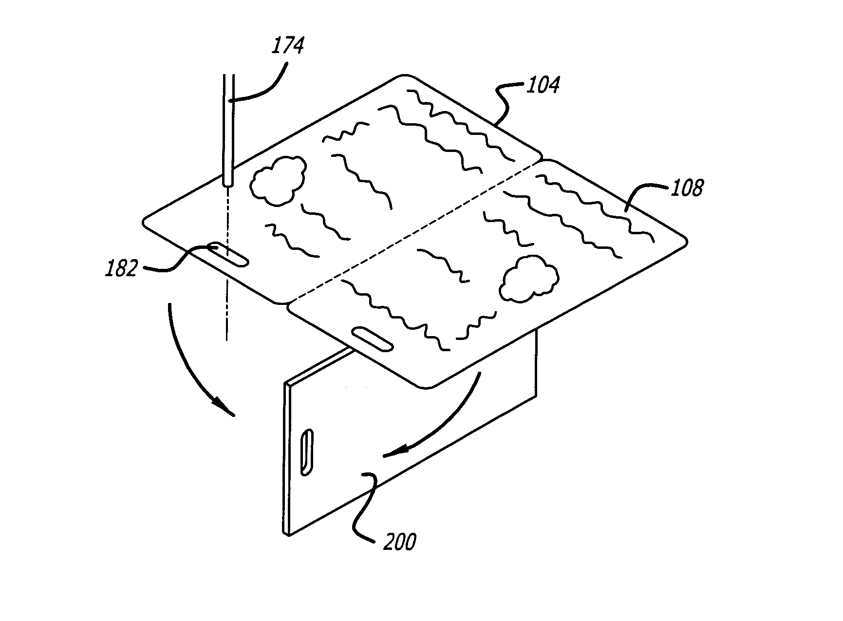
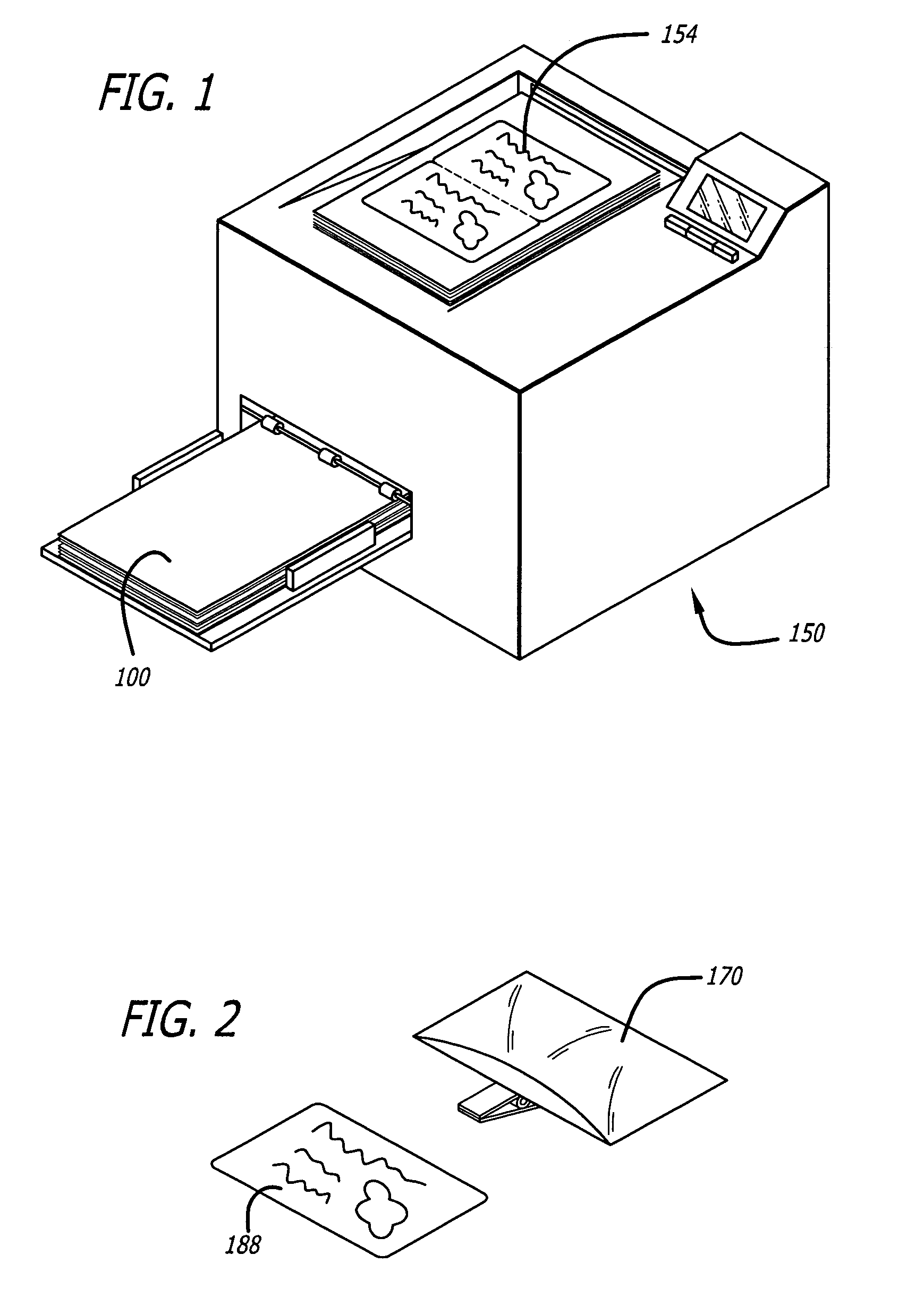
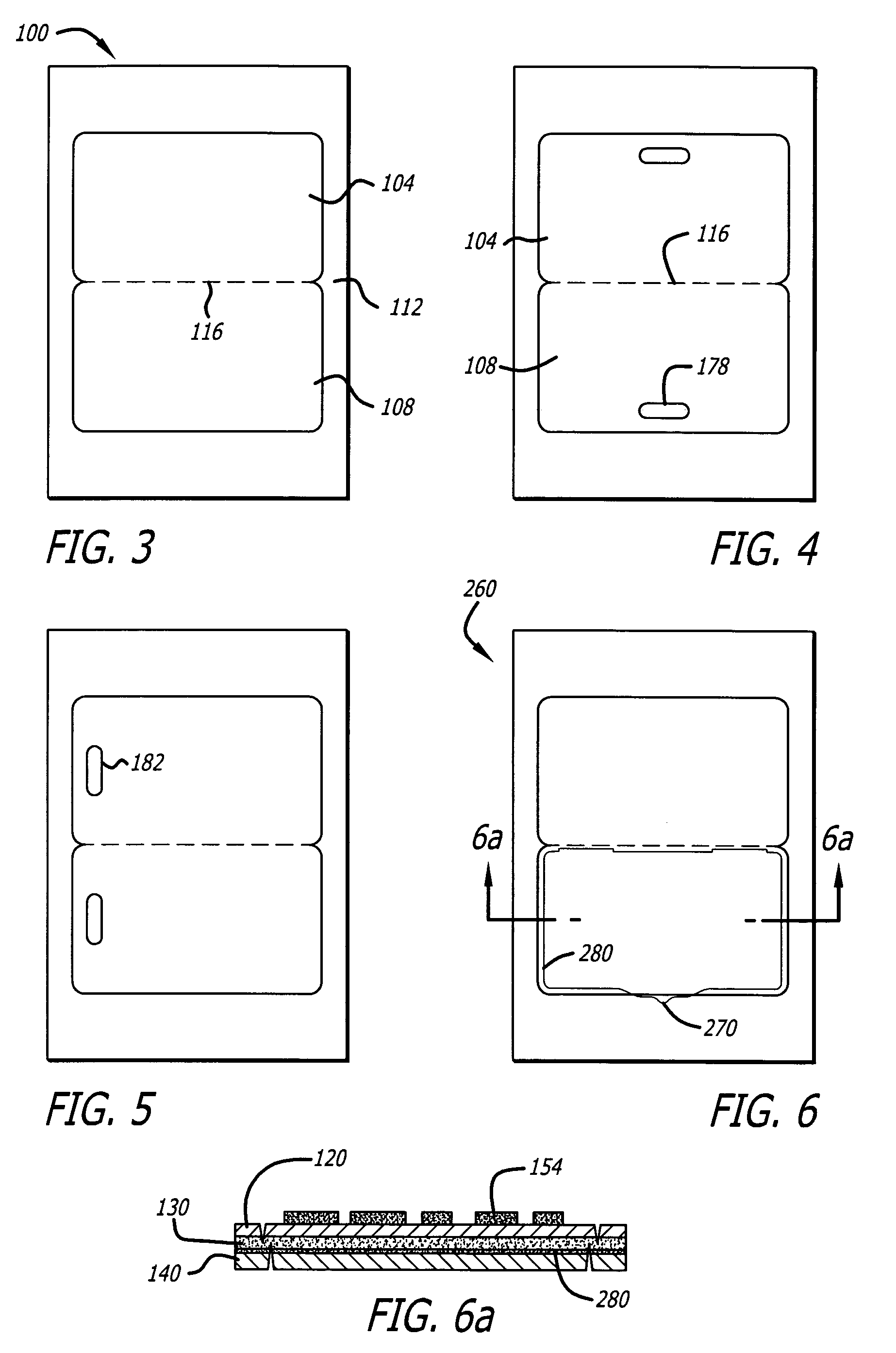
[0086]Referring to FIG. 3, the present invention shown generally at 100 includes two adjacent badge size labels 104, 108 on a sheet 112, attached at the joining point by a perforation 116. This embodiment can be made of a facestock 120, adhesive 130 and a silicone coated liner 140 in FIG. 6a and can be used in different ways. The first way is that after it has been printed upon such as by a printer or a copier 150 (see FIG. 1), it can be removed from the carrier sheet and simply folded at the perforation 116. This provides a two layer construction with some of the properties of a card, but it would have been printed with indicia 154 on both sides with a single pass through the printer or copier (see FIG. 1 at 150). This can then be removed and inserted into a carrier, such as shown in FIG. 2 at 170 and as is known in the prior art. The two-sided card can also be suspended from a lanyard 174 (FIG. 51) if holes 178, 182 are included either on the top and bottom or on the sides as show...

third embodiment

[0102]A third embodiment shown generally at 500 in FIG. 10 is designed to be applied to one side of an RFID card 200 or some similar device such as depicted in FIG. 51. This embodiment would be printed on the liner side 510 in an inkjet or laser printer as can be understood from FIG. 10a. The printed liner section 520 can be removed, flipped over, as shown in FIG. 10b, and reinserted into the area from which it was removed, as can be understood from FIG. 11 at 530. The printed indicia 534 is visible through the transparent film 538. The entire center section 540 can then be removed, as shown in FIG. 11a, and applied to an RFID card, as the exposed adhesive area 550 around the centered printed card bonds the center section to the RFID card or other device.

[0103]First and second alternative embodiments to construction shown in FIG. 10 are shown in FIGS. 12 and 13, at 580 and 590, respectively. They can have hanger holes 600, 604 that are cut through the face and liner and are attached...


PUM

PropertyMeasurementUnit
sizeaaaaaaaaaa
sizeaaaaaaaaaa
sizeaaaaaaaaaa

Abstract

A label badge sheet construction including a facestock sheet releasably adhered to a liner sheet. A weakened separation line in the facestock sheet defines at least one label. After the sheet construction has been passed through a printer or copier and desired indicia printed on the at least one label the printed label can be removed to be used as a visitor's badge or the like. Preferably, first and second labels are formed with a fold line separating them, and a weakened separation line through the liner sheet forms a liner panel which is adhered to the back of the first label. With the first and second labels and the liner panel removed as a label assembly and the labels folded on the fold line, through-holes through the first and second labels and the liner panel are aligned. A lanyard or clip can be passed through the aligned through-holes. The liner panel thereby reinforces the through-holes. The invention further includes the assembled label badge, the method of forming same, the method for manufacturing the sheets and the kit which includes sheets, software, hardware, etc.

Description

CROSS-REFERENCE TO RELATED APPLICATIONS[0001]This application claims priority from the following U.S. Provisional Applications: Ser. No. 60 / 446,817, filed Feb. 11, 2003; Ser. No. 60 / 411,268, filed Sep. 16, 2002; Ser. No. 60 / 432,941, filed Dec. 11, 2002; and Ser. No. 60 / 466,689, filed Apr. 30, 2003. The entire contents of all of these applications are incorporated by reference.FIELD OF THE INVENTION[0002]This invention relates to the field of identification badges. More particularly, this application relates to the field of identification badge construction and printing.BACKGROUND OF THE INVENTION[0003]Visitor management has been addressed in many different ways. One of the most common is a self-adhesive name badge. Although there are certain advantages to having a badge inserted into a clear plastic sleeve and suspended from a lanyard or attached to visitor's clothing via a clip, or placed into a badge carrier of some sort, a standard label cannot be used for such an application. Th...

Claims


Application Information

Patent Timeline
Patent Type & Authority Patents(United States)
IPC IPC(8): B32B9/00A44C3/00B32B33/00B42D15/00G09F3/00B42D15/10G06K19/04G07F17/26G09F3/02G09F3/10G09F3/14G09F3/20
CPCG06K19/041G07F17/26G09F3/0288G09F3/10G09F3/14G09F3/207G06K19/07758Y10T428/24802Y10T428/24934Y10T428/149Y10T428/24314Y10T428/14Y10T428/1476Y10T428/1486Y10T428/24322Y10T428/1495Y10T428/15
Inventor BANKS, DONALD E.HODSDON, JERRY G.UGOLICK, RONALD
Owner CCL LABEL INC
Why Eureka
Try Eureka