Safety stand and knife and method of use

a safety stand and knife technology, applied in the field of safety stand and knife and method of use, can solve the problems of user's care level being lowered, electric knife blades typically cannot be stored in conventional knife blocks for single bladed knives, and electric knives may not know the correct pressur

Inactive Publication Date: 2009-05-26
RICHMOND DAVID JOSEPH +2
View PDF8 Cites 6 Cited by
  • Summary
  • Abstract
  • Description
  • Claims
  • Application Information

AI Technical Summary

Benefits of technology

[0018]FIG. 7 illustrates steps for safely inserting one or more knife blades into a knife handle, according to one method of the invention

Problems solved by technology

However, a user may lower this level of care when inserting the blades into the knife's handle or removing them, and so may cut themselves inadvertently on the exposed knife's serrated edges.
Consequently, a set of electric knife blades typically can't be stored in conventional knife blocks for single bladed knives.
Without safe storage, removable blades are often kept loose in a utensil drawer or some container.
But children are known for reaching up onto kitchen counters or into drawers and grabbing at harmfu

Method used


Image

  • Safety stand and knife and method of use
  • Safety stand and knife and method of use
  • Safety stand and knife and method of use

Examples


second embodiment

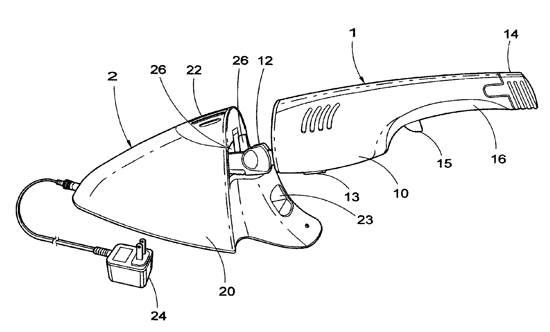
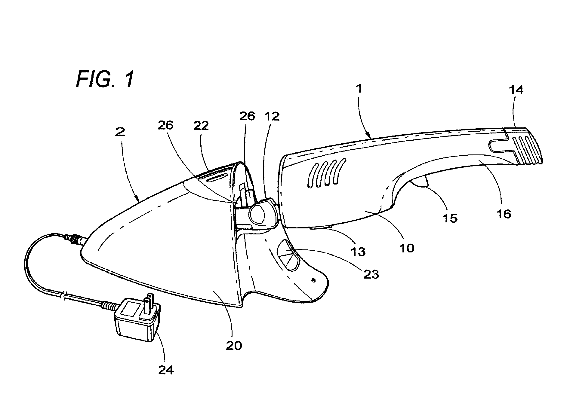
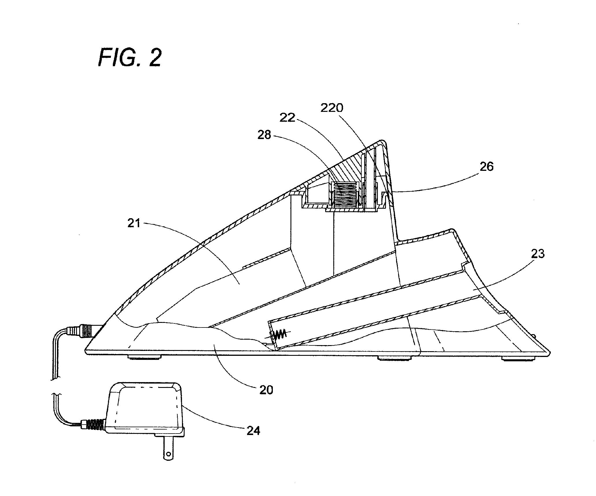
[0033]In the invention, not shown in the drawings, the connector 28 is resilient. The term “connector” does not require that a resilient connector 28 be permanently connected to either the safety stand 2 or the blade lock 22. Together, blade lock 22 and safety stand 2 define at least one blade opening 26 configured to permit at least one blade 12 to pass there through without displacement of the blade lock 22.

[0034]When the lock 22 is pressed down flush with the stand base 20, the rear edge 130 of the lock sentry 128 is configured to abut an inner wall 220 of the blade lock 22, and to prevent removal of blades 12 from the blade opening 26 as long as downward pressure on the lock 22 is maintained. When so positioned and a blade removing force is exerted on the blades 12, the lock 22 retains the blades 12 as long as the lock 22 remains pressed and in the abutment position described above. The height h, the applied downward force, and the configuration of the rear edge of the lock sent...

first embodiment

[0037]With reference now to FIG. 7, to remove blades 12 retained in the safety stand 2 of the first embodiment, one of two methods may be used. The blade lock 22 may be pulled upwards with one hand while the blades 12 are removed using the other hand. Alternately, a user firmly stabilizes the stand 2 with one hand while exerting a removing force on the blades 12 with the other hand.

[0038]The stands in either embodiment are further configured to balance and hold an assembled knife 1 by its blades 12 within the safety stand 2, to hold blades 12 alone within the stand 2, or to hold a combination of blades 12 and an assembled knife 1. There is no apparent limit to the number of blade openings 26 that a stand 2 may have.


PUM


Abstract

The invention provides a safety stand for storing one or more knives or knife blades. The stand may have a lock that automatically retains inserted blades or knives and prevents their inadvertent removal. The invention also provides for methods of using the stand for inserting and removing knife blades without a user having to touch the blade itself, thereby reducing the risk of being cut.

Description

BACKGROUND[0001]Like kitchen knifes used for slicing bread or for carving meat and fish, rechargeable battery operated kitchen knives have become necessary in most homes. Such knives typically comprise a knife handle containing a motor and batteries and employ a pair of slideably disposed, serrated knife blades to cut food by reciprocating action. The set of blades is removably fixed into the knife handle and powered by the motor. The blades are typically sharp, move rapidly when in use, and are inserted into and removed from the knife handle by hand.[0002]Users are often careful not to cut themselves while using such knives to cut food, recognizing the danger of the moving blades. However, a user may lower this level of care when inserting the blades into the knife's handle or removing them, and so may cut themselves inadvertently on the exposed knife's serrated edges. The chances of being cut increase each time a set of blades is handled, and each set is typically handled twice pe...

Claims


Application Information

Patent Timeline
IPC IPC(8): A47F5/16A47F7/00
CPCA47G21/14B26B7/005
Inventor RICHMOND, DAVID JOSEPHFERNANDEZ, JUANMCGRATH, PAUL
Owner RICHMOND DAVID JOSEPH
Why Eureka
Try Eureka