Supercharge Your Innovation With Domain-Expert AI Agents!

Image forming projection system and projector using input and output signals

a projection system and input signal technology, applied in the field of projection system and projector, can solve the problems of inability to adjust based on the detection of such adjustment operation signals, and the inability of the computer to recognize the type of projector to which it is connected, so as to reduce the processing of the projector and reduce the production cost of the projector

Inactive Publication Date: 2009-05-26
COLUMBIA PEAK VENTURES LLC
View PDF10 Cites 1 Cited by
  • Summary
  • Abstract
  • Description
  • Claims
  • Application Information

AI Technical Summary

Benefits of technology

[0018]However, even when the projector has an image processor, this invention increases the usability because it makes it possible for higher-level image processing provided by the connected computer to be adjusted by the operation section such as a remote controller.
[0023]In this case, when the system exits, adjustment information set by the image processor of the computer is stored in the projector. Accordingly, the computer can call the adjustment information at the next startup and adjustment the settings, thus providing an easy-to-use projection system.
[0025]In this case, the settings on the projector can be made by the computer. This allows the adjustment of the settings by the projector to be omitted, thus reducing the processing by the projector and thus decreasing the production cost of the projector.

Problems solved by technology

Accordingly, even when operation buttons or remote controllers are used to adjust image quality, adjustment cannot be carried out based on such adjustment operation signals detected in the projector.
Without the individual-difference-information storage section, the computer cannot recognize the kind of projector to which it is connected.

Method used


Image

  • Image forming projection system and projector using input and output signals
  • Image forming projection system and projector using input and output signals
  • Image forming projection system and projector using input and output signals

Examples


Embodiment Construction

[0032]The invention will be described with reference to the accompanying drawings, wherein like numbers reference like elements.

[0033]An embodiment of the invention will be described with reference to the drawings.

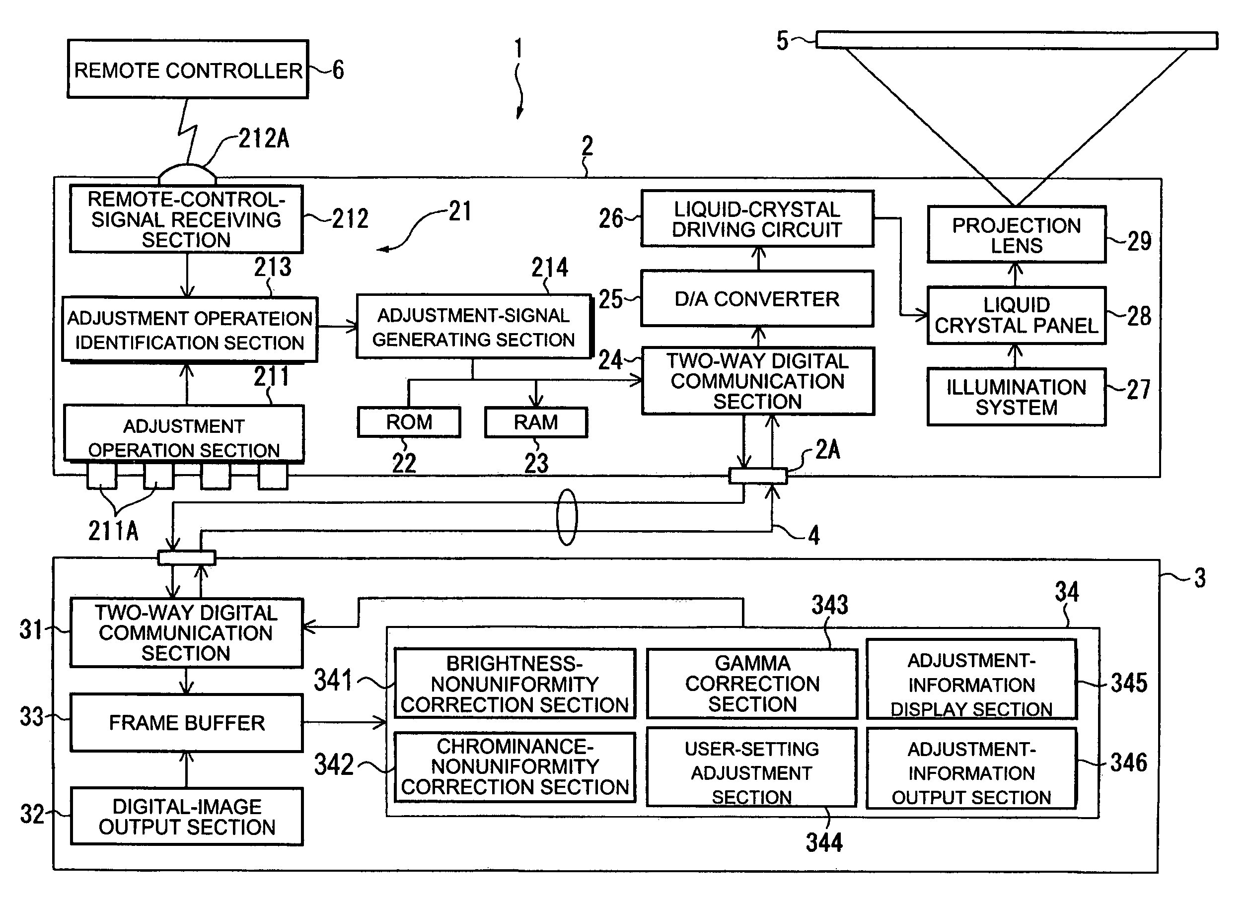
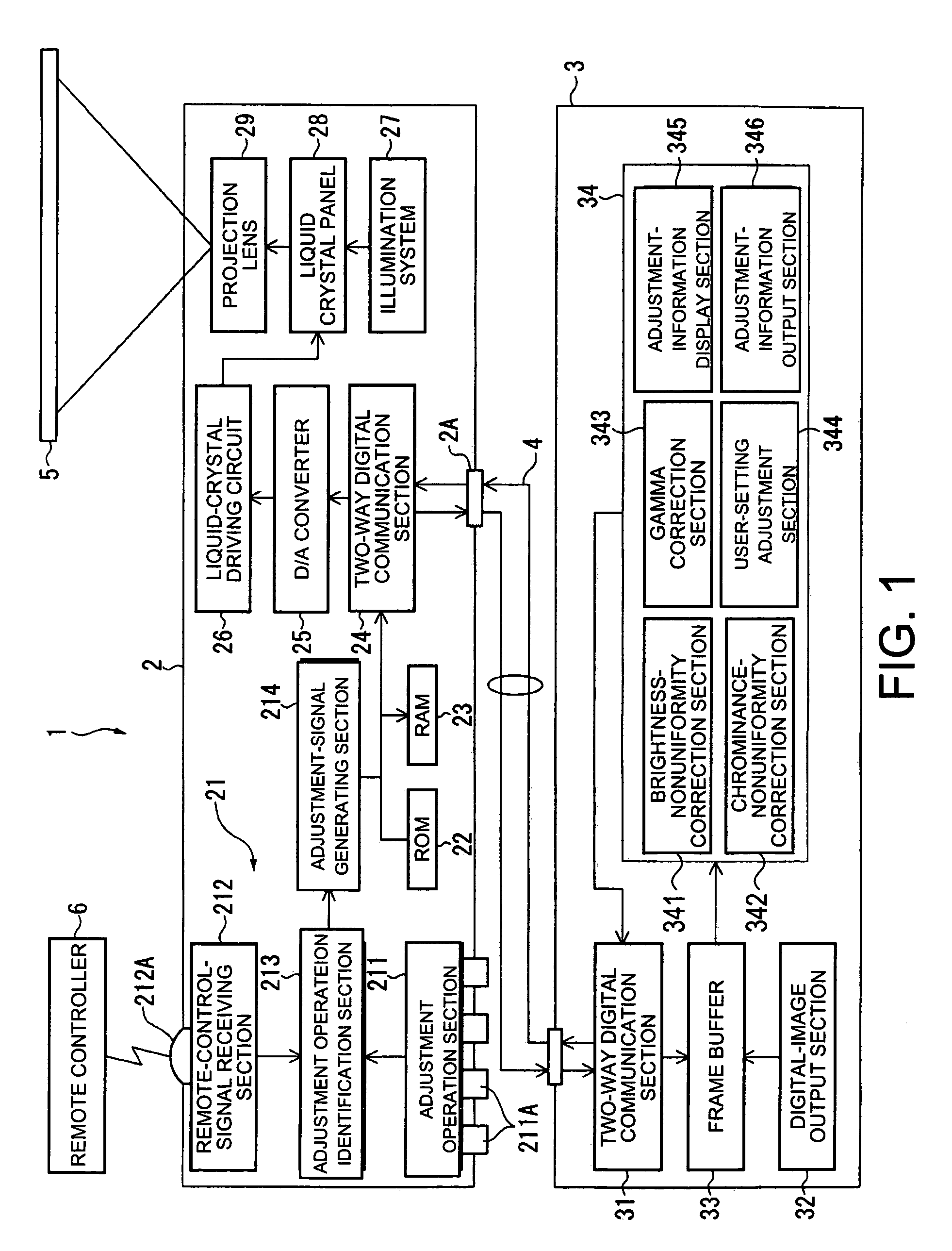
[0034]FIG. 1 shows a projection system 1 according to an embodiment of the invention.

[0035]The projection system 1 is a device in which a projector 2 and a computer 3 are connected to each other with a USB cable 4. The projection system 1 outputs a digital image signal from the computer 3 to the projector 2 via the USB cable 4, and projects it on a screen 5.

[0036]The USB cable 4 is based on the USB 1.1 or USB 2.0 standard and is capable of two-way communication between connected devices.

1. Structure of the Projector

[0037]The projector 2 modulates the light emitted from a light source according to input image information to form an optical image, and projects the image on the screen 5 in a magnified form. The projector 2 includes a user operation system 21, a ROM 22, a RAM ...


PUM


Abstract

A projection system includes a projector and a computer connected to the projector, wherein the projector projects an image according to an image information output from the computer. The projector includes an adjustment operation section that adjusts the settings of the projector and an adjustment operation identification section that identifies the adjustment operation indicated by an adjustment signal output from the adjustment operation section. The projector includes an adjustment-signal generating section that generates an adjustment signal on the basis of the adjustment operation identified by the adjustment operation identification section and a two-way communication section that sends the generated adjustment signal to the computer, and receives a signal from the computer. The computer includes a two-way communication section that receives the adjustment signal and sends a signal and an image processor that processes the image signal to be output according to the received adjustment signal.

Description

BACKGROUND[0001]1. Technical Field[0002]The present invention relates to projection systems and projectors for use in the projection systems. The projection systems include: a projector that modulates the light emitted from a light source according to image information to form an optical image, and projects the image in a magnified form, and a computer connected to the projector via a signal input and output terminal. In the projection systems the projector projects an image based on the image information output from the computer.[0003]2. Related Art[0004]Known projectors generally modulate the light emitted from a light source according to image information to form optical images, and project them in a magnified form. Such projectors form optical images on the basis of input image information by controlling light modulators such as liquid crystal panels, and project them in a magnified form.[0005]The light modulators such as liquid crystal panels differ in their applied voltage—lig...

Claims


Application Information

Patent Timeline
Patent Type & Authority Patents(United States)
IPC IPC(8): G03B21/14G06K9/40G03B29/00
CPCH04N5/7416H04N9/3182H04N9/3185
Inventor SAITO, TOSHIKI
Owner COLUMBIA PEAK VENTURES LLC
Features
  • R&D
  • Intellectual Property
  • Life Sciences
  • Materials
  • Tech Scout
  • Unparalleled Data Quality
  • Higher Quality Content
  • 60% Fewer Hallucinations
Learn More