Angled mini arm having a clevis assembly

a mini arm and assembly technology, applied in the field of compact and versatile extension arms, can solve the problems of reducing the available workspace occupied by equipment, inability to place equipment in a desired location, eye strain, neck strain, etc., and achieve the effect of preventing loosening

Active Publication Date: 2009-06-02
HUMAN ACTIVE TECH LLC
View PDF36 Cites 54 Cited by
  • Summary
  • Abstract
  • Description
  • Claims
  • Application Information

AI Technical Summary

Benefits of technology

[0029]In accordance with another embodiment of the present invention, an extension arm apparatus for supporting a user device is provided. The apparatus comprises first and second endcaps, first and second channels, and a forearm assembly. The first endcap has a first section for connection to a mount and a second section connected to the first section thereof. The second endcap also has first and second sections. The first channel has first and second ends. The first end of the first channel is connected to the second section of the first endcap and the second end of the first channel is connected to the first section of the second endcap. The second channel has first and second ends. The first end of the second channel is connected to the second section of the first endcap and the second end of the second channel is connected to the first section of the second endcap. The first and second channels defining a receptacle for a spring device. The forearm assembly includes an anti-loosening apparatus and a forearm extension. The forearm extension has a first end operatively coupled to the second section of the second endcap and a second end for supporting the user device. The anti-loosening apparatus permits rotation of the forearm extension relative to the second endcap while preventing loosening between the forearm extension and the second endcap during rotation.
[0030]In one alternative, the second section of the second endcap includes a receptacle having an opening therein, the first end of the forearm extension includes a shaft and at least one recess disposed in the shaft, the shaft is at least partly received within the opening in the second section of the second endcap, and the forearm assembly further comprises a washer and a fastener. The washer has at least one protrusion adapted to be received within the at least one recess to connect the washer to the shaft. The fastener secures the second section of the second endcap, the washer and the shaft together so that the shaft is rotatable relative to the second section of the second endcap.
[0033]In accordance with a further embodiment of the present invention, an extension arm apparatus for supporting a user device is provided. The apparatus comprises first and second endcaps, first and second channels and a forearm extension. The first endcap has means for mounting to a surface. The first channel has first and second ends. The first end of the first channel is connected to the first endcap and the second end of the first channel is connected to the second endcap. The second channel has first and second ends. The first end of the second channel is connected to the first endcap and the second end of the second channel is connected to the second endcap. The forearm extension has first and second ends. The first end of the forearm extension is operatively coupled to the second endcap. The second end of the forearm extension is operatively coupled to the user device. The apparatus further includes means for preventing loosening between the forearm extension and the second endcap.
[0034]In accordance with yet another embodiment of the present invention, an extension arm apparatus for positioning a user device is provided. The apparatus comprises first and second housings, a channel assembly, a supporting device and a connection assembly. The first housing is used to secure the extension arm apparatus to a support. The second housing is remote from the first housing and includes a receptacle therein. The channel assembly connects the first and second housings and is adjustable to change positioning of the extension arm apparatus. The supporting device is connectable to the user device and includes a first connecting member on a surface thereof. The connection assembly is used for connecting the supporting device to the second housing. The connection assembly includes a washer and a fastener. The washer has an opening therethrough and a second connecting member on a first surface thereof. The second connecting member secures to the first connecting member of the supporting device. The fastener is insertable through the opening of the washer and the receptacle of the second housing to threadedly engage the supporting device. The supporting device is rotatable about the second housing while the first and second connecting members prevent loosening of the supporting device relative to the second housing.

Problems solved by technology

One drawback to these configurations is the reduction in available workspace taken up by the equipment.
Another drawback is the inability to place the equipment in a desired location.
A further drawback is the potential for eye strain, neck strain and / or a cumulative trauma disorder such as carpel tunnel syndrome from poor placement of devices such as monitors and keyboards.
While this may free up workspace, it often places the equipment in an undesirable location.
Known extension arms, such as those in FIGS. 1-7, may operate satisfactorily, but may not be well suited for sleeker, more compact designs.
Reducing the size of some components can, if not correctly engineered, adversely impact equipment performance.
Unfortunately, if the overall structure of the extension arm remains the same as the size is reduced, a smaller gas spring typically cannot handle the load of a large device, and, in turn, cannot support larger monitors or other equipment.
Loose connections could potentially lead to hazardous conditions.

Method used


Image

  • Angled mini arm having a clevis assembly
  • Angled mini arm having a clevis assembly
  • Angled mini arm having a clevis assembly

Examples


Embodiment Construction

[0065]In describing the preferred embodiments of the invention illustrated in the appended drawings, specific terminology will be used for the sake of clarity. However, the invention is not intended to be limited to the specific terms used, and it is to be understood that each specific term includes all technical equivalents that operate in a similar manner to accomplish a similar purpose.

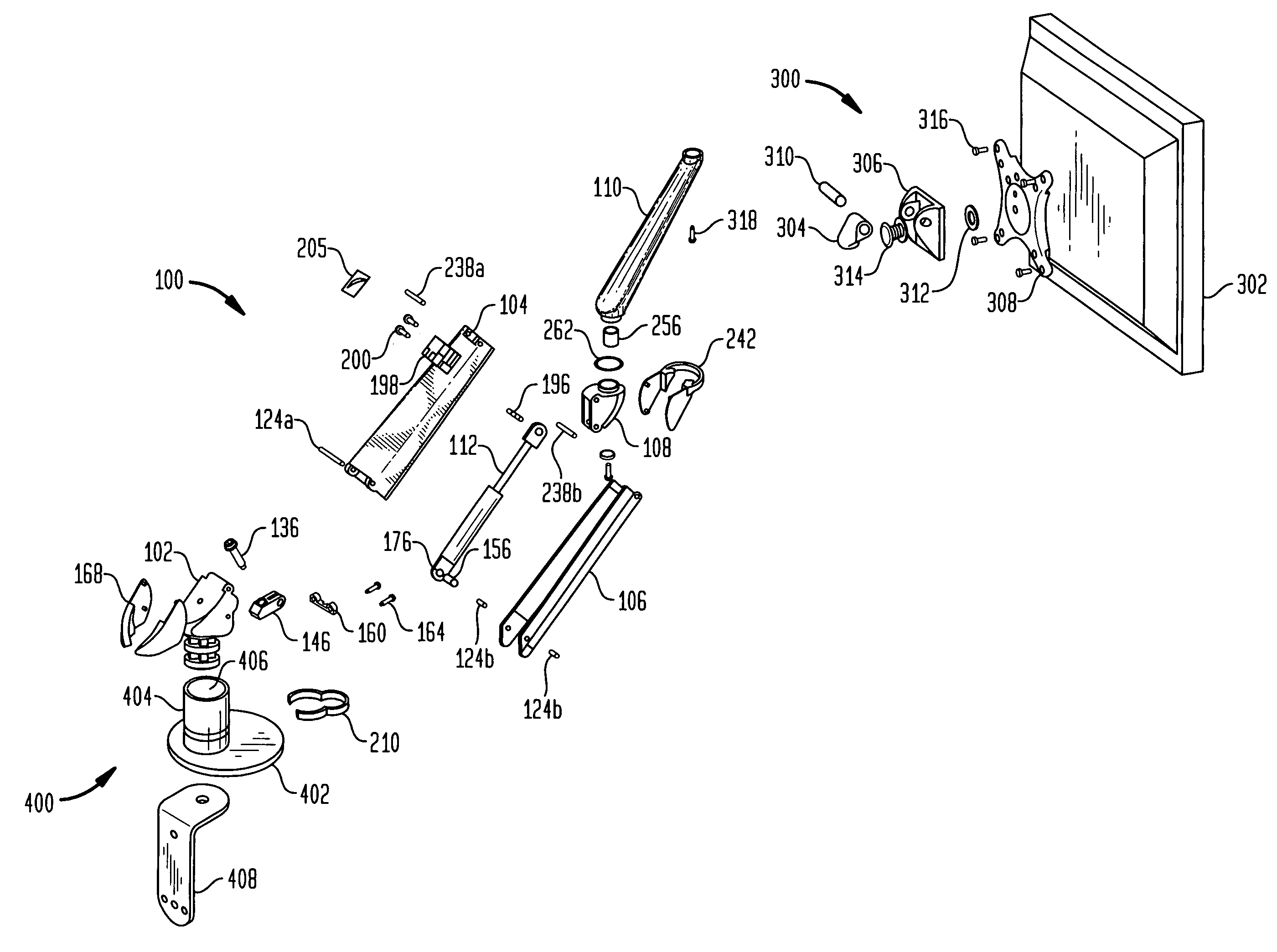
[0066]FIG. 8 illustrates an extension arm 100 in accordance with a preferred embodiment of the present invention. The extension arm 100 is connectable at one end to a mounting assembly 400 and attachable to a tilting device 300 at the other end. The mounting assembly 400 may be of any desired configuration, and may be affixed to a piece of furniture such as a desk, a wall such as a slat wall, a section of an office cubicle, etc. The tilting apparatus 300 is connectable to a user device 302 such as a flat panel monitor, although other electronic or non-electronic devices may connect to the tilting a...


PUM


Abstract

The present invention provides an extension arm apparatus with angled clevis operation to provide enhanced mechanical leverage. The clevis adjusts along a path angled relative to an axis of the device, which significantly boosts performance and can reduce the size of the apparatus. Upper and lower channels of the device taper from a first width to a second width, providing a sleek and functional apparatus that can be used with heavy monitors, displays or other user equipment. When a forearm extension attached to an endcap of the apparatus, an interlocking washer and shaft configuration prevents the forearm extension-endcap connection from loosening during operation.

Description

CROSS-REFERENCE TO RELATED APPLICATION[0001]This application is related to U.S. patent application Ser. No. 11 / 141,425, filed concurrently herewith and entitled “TAPERED MINI ARM HAVING AN ANTI-LOOSENING MECHANISM,” the entire disclosure of which is hereby expressly incorporated by reference herein.BACKGROUND OF THE INVENTION[0002]The present invention relates to a device for use in connecting electronic and other user devices. More particularly, the present invention relates to compact and versatile extension arms on which electronic devices such as flat panel displays, keyboards, etc. can be mounted.[0003]In the past people have placed video monitors and other electronic equipment on desks, tabletops, or upon other equipment such as personal computers or workstations. One drawback to these configurations is the reduction in available workspace taken up by the equipment. Another drawback is the inability to place the equipment in a desired location. A further drawback is the potent...

Claims


Application Information

Patent Timeline
Patent Type & Authority Patents(United States)
IPC IPC(8): E04G3/00
CPCF16M11/04F16M11/06F16M11/105F16M11/2064F16M11/2092F16M11/24F16M13/022F16M2200/063Y10S248/921Y10S248/922
Inventor ODDSEN, JR., ODD N.DERRY, BRADLEY A.
Owner HUMAN ACTIVE TECH LLC
Why Eureka
Try Eureka